
Sink geophysical prospecting testing device with variable spacing
A test device and spacing technology, applied in the field of geophysical exploration, can solve the problems of difficulty in improving accuracy, large errors, and difficulty in forming holes, etc., and achieve the effect of reliable testing
Patent Information
- Authority / Receiving Office
- CN · China
- Patent Type
- Applications(China)
- Current Assignee / Owner
- Publication Date
- 2016-12-07
- Estimated Expiration
- Not applicable · inactive patent
Smart Images
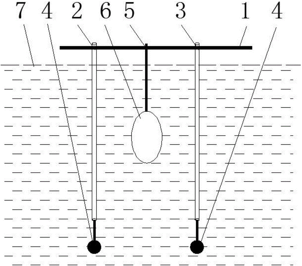
Figure 1
Abstract
Description
technical field
[0001] The invention relates to a water tank geophysical prospecting test device with variable spacing, and belongs to the technical field of geophysical prospecting. Background technique
[0002] There are two types of existing inter-hole geophysical testing methods. The first type is on-site geophysical testing, which is also the main type currently used. It is characterized by selecting a testing site and conducting geophysical testing on the testing site to form holes. The spacing and depth are generally several meters to tens of meters. Afterwards, according to the geophysical test requirements, acoustic tomography (CT) and penetration, seismic tomography (CT) and penetration, and electromagnetic tomography (CT) and transmission can be carried out between holes. The other is the indoor model test. According to the needs, a specific model is made in a certain proportion indoors and holes are formed. Acoustic tomography (CT) and penetrating geophysical te...
Examples
Embodiment Construction
[0015] The technical scheme of the present invention will be further described below in conjunction with the accompanying drawings, but the required protection scope is not limited to the description;
[0016] Such as figure 1 As shown, the water tank geophysical test device with variable spacing provided by the present invention includes a horizontal sliding groove 1 fixed above the medium water body 7, and two through holes arranged at intervals are opened on the horizontal sliding groove 1, and the through holes are respectively inserted into There are a fixed tube 2 and a moving tube 3, the bottom ends of the fixed tube 2 and the moving tube 3 are fixedly connected with a vertical positioning hammer 4, the lower side of the middle part of the horizontal sliding groove 1 is equipped with a fixed rod 5, and the end of the fixed rod 5 is equipped with a model 6 , the model 6 is placed in the medium water body 7 .
[0017] The fixed tube 2 and the moving tube 3 are vertical t...