
Human gait energy-conversion power generating device
An energy conversion and power generation device technology, applied in electromechanical devices, electrical components, machines/engines, etc., can solve the problems of difficult maintenance, complex structure, and high cost, and achieve improved structural stability, simple structure distribution, and high production efficiency. Effect
Patent Information
- Authority / Receiving Office
- CN · China
- Patent Type
- Applications(China)
- Current Assignee / Owner
- Publication Date
- 2017-02-01
Smart Images
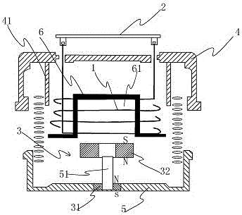
Figure 1 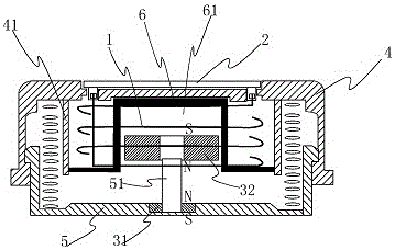
Figure 2 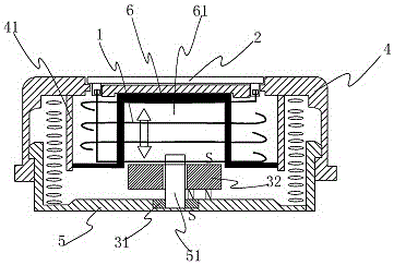
Figure 3
Abstract
Description
technical field
[0001] The invention relates to a power generation device, in particular to a human body gait energy conversion power generation device. Background technique
[0002] With the continuous development of information technology, the era of the Internet of Things has come. The Internet of Things is an important part of the new generation of information technology, and it is also an important stage of development in the "informationization" era. The Internet of Things is the Internet where things are connected, and its client end extends and expands to information exchange and communication between any item and item. With the maturity of technology, human body wearable smart equipment has been continuously developed and widely used. Smart chips located on watches, shoes, clothes, and even backpacks can be connected through the mobile APP to monitor human GPS positioning, movement trajectory, step counting, heartbeat, temperature, etc. at all times.
[0003] At ...
Examples
Embodiment Construction
[0021] The present invention will be further described in conjunction with the accompanying drawings and specific embodiments.
[0022] refer to Figure 1 to Figure 4 , the embodiment of the present invention discloses that the human body gait energy conversion power generation device includes an electromagnetic induction coil 1, a rectification cache chip 2 connected with the electromagnetic induction coil and a permanent magnet 3, and also includes an upper slide cover 4, a lower base 5 and a The coil base 6, the upper sliding cover 4 and the lower base 5 are connected through a sliding structure that can slide under force to generate damping compression; the upper sliding cover 4 is provided with an isolation cavity 41, and the coil base 6 is set in the isolation cavity 41, a coil protection cavity is formed between the coil base 6 and the inner cavity wall of the isolation cavity 41, and the electromagnetic induction coil 1 is arranged around the outer wall of the coil bas...