
Rotary vibrating table and system
A technology of turntable and shaking table, applied in vibration testing, measuring devices, instruments, etc., can solve the problems of high minimum measurement frequency, low bearing capacity, and high price of shaking table, and achieve low minimum measurement frequency, high bearing capacity, simple structure
Patent Information
- Authority / Receiving Office
- CN · China
- Patent Type
- Applications(China)
- Current Assignee / Owner
- Publication Date
- 2017-05-10
Smart Images
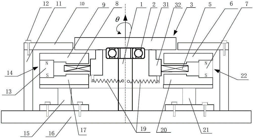
Figure 1 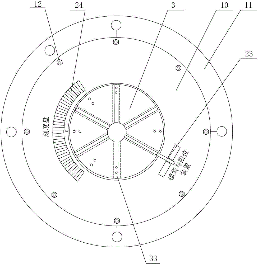
Figure 2 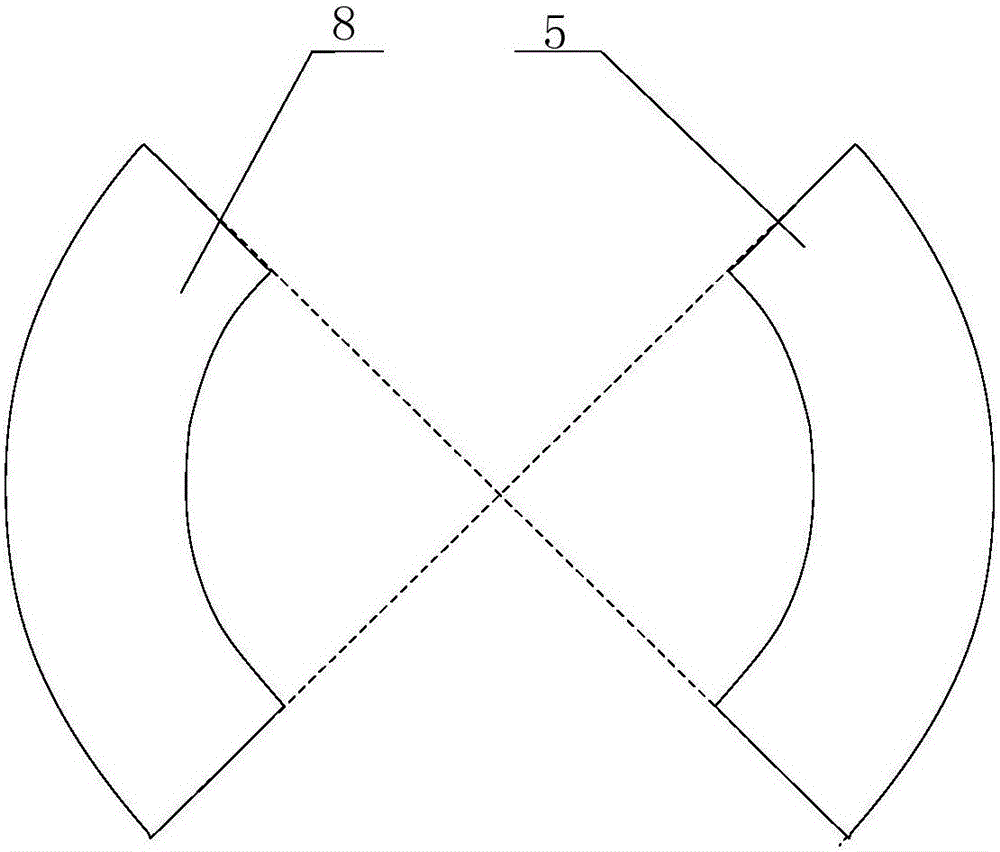
Figure 3
Abstract
Description
technical field
[0001] The invention relates to the technical field of measuring and calibrating equipment, in particular to a rotating vibrating table and a system thereof. Background technique
[0002] At present, there are angular vibration vibrating tables driven by torque motors at home and abroad. The measurement principle is generally calibrated once by laser interferometry, and the frequency range is 5Hz-500Hz; but the vibrating table is expensive and the minimum measurement frequency is high. In addition, the bearing capacity of the current angular vibration table is generally less than 10kg, which can only be used for the calibration of general angular vibration sensors, and cannot be used for the calibration of larger seismic rotation sensors and the anti-torsional vibration test of small-scale structures.
[0003] Therefore, there is an urgent need for a relatively low-cost, low-minimum measurement frequency, and high-capacity rotational vibration table and its s...
Examples
Embodiment 1
[0045]see Figure 1-Figure 8 As shown, the present embodiment provides a rotary vibrating table; figure 1 The first angle sectional view of the rotary vibrating table provided for this embodiment (the hatching is not shown in the figure); figure 2 Schematic diagram of the second angle structure of the rotary vibrating table provided in this embodiment; image 3 Schematic diagram of the structure of the drive coil and feedback coil of the rotary vibrating table provided in this embodiment; Figure 4 Schematic diagram of the structure of the driving permanent magnet and the feedback permanent magnet of the rotary vibrating table provided in this embodiment; Figure 5 Schematic diagram of the structure of the drive magnetic circuit and the feedback magnetic circuit of the rotary vibrating table provided in this embodiment; Figure 6 A cross-sectional view of the drive coil or feedback coil of the rotary vibrating table provided in this embodiment (only the label of the drive ...