
Ultraviolet light source assembly, ultraviolet optical system and ultraviolet printing device
A technology for an ultraviolet light source and an optical system, which is applied in the fields of ultraviolet light source components, ultraviolet optical systems and ultraviolet printing devices, can solve the problems of difficult heat dissipation, high manufacturing and use costs, and low reliability, and achieves simplified structure and improved reliability. , The effect of reducing the difficulty of heat dissipation
Patent Information
- Authority / Receiving Office
- CN · China
- Patent Type
- Applications(China)
- Current Assignee / Owner
- Publication Date
- 2017-05-17
Smart Images
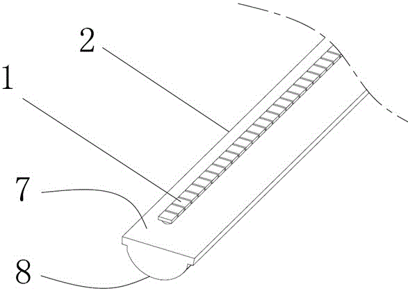
Figure 1 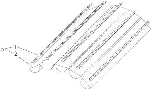
Figure 2 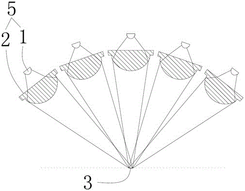
Figure 3
Abstract
Description
technical field
[0001] The invention relates to the field of ultraviolet light application technology, in particular to an ultraviolet light source assembly, an ultraviolet optical system and an ultraviolet printing device. Background technique
[0002] Ultraviolet light is widely used in ultraviolet exposure, ultraviolet lithography, ultraviolet printing, ultraviolet curing and other industries. In these industries, the characteristics of short wavelength and high photon energy of ultraviolet light are used. Therefore, in the field of ultraviolet light application technology , have higher requirements on the irradiation energy of ultraviolet light.
[0003] At present, in order to increase the energy intensity of the area irradiated by ultraviolet light, it is usually adopted to arrange multiple ultraviolet light sources, such as Figure 9 As shown, a large number of ultraviolet light sources are arranged in sequence, and the ultraviolet light emitted by these ultraviolet l...
Examples
Embodiment 1
[0055] Embodiment 1: as figure 1 and 3 as shown,
[0056] An ultraviolet light source assembly, including several light sources 1 for emitting ultraviolet light, and also includes a light collection device 2, the light collection device 2 cooperates with the light source 1, so that each light source 1 emits all or part of the light After entering the light collecting device 2, the light collecting device 2 converges the light entering into a plane, and forms a continuous strip-shaped irradiation area 3 in the plane.
[0057] In the field of ultraviolet light application technology, for the traditional ultraviolet light source assembly 5, it is a plurality of light sources 1, in the state of free light, superimposed on a working surface for printing work, and the ultraviolet light source assembly 5 of the present application , using the light collection device 2 to collect and collect the light emitted by the light source 1, and form a continuous strip-shaped irradiation are...
Embodiment 2
[0061] Example 2, such as Figure 1-5 Shown:
[0062] Based on the structure of Embodiment 1, the light collecting device 2 is a lens. The lens is used as the light collection device 2 , the lens has good integrity, which further simplifies the structure, and the shape of each optical surface of the lens is well controlled, so that the light can be adjusted conveniently.
[0063] As an implementation manner, each of the light sources 1 is arranged in a straight line.
[0064] In the above-mentioned scheme of the present application, each light source 1 is arranged on the same straight line, so as to facilitate the formation of a straight-line irradiation area or a straight-line continuous linear light strip 4, and the length of the light strip 4 is the same as that of the printed article and the photoetched object. The length or width of the piece or the piece to be exposed is matched, so that when the light source assembly 5 moves relatively with the piece to be printed, th...
Embodiment 3
[0068] Example 3, such as Figure 6 , 8 and 9 as shown:
[0069] Based on the structure of Embodiment 1, the light collecting device 2 is a reflector.
[0070] As an embodiment, the reflector has a cylindrical reflective surface, each of the light sources 1 is arranged in the reflector, and the reflector gathers the light irradiated thereon and reflects it to the A strip-shaped irradiation area 3 or a continuous linear light strip 4 .
[0071] In this embodiment, the light collection device 2 can also use a reflector. When a reflector is used, the reflective surface of the reflector collects and gathers the light emitted by the light source 1. In this way, it also forms a strip with higher energy intensity as described above. Irradiate the area 3 or the continuous linear light strip 4, so that fewer light sources 1 can be used;
[0072] When the reflector structure is adopted, the light source 1 is located in the reflector, so that, on the one hand, all the light emitted b...