
Underground gravity heat pipe direct heating device
A gravity heat pipe and heating device technology, applied in the field of heating devices, to achieve the effect of no operating costs
Patent Information
- Authority / Receiving Office
- CN · China
- Patent Type
- Applications(China)
- Current Assignee / Owner
- Publication Date
- 2017-05-24
- Estimated Expiration
- Not applicable · inactive patent
Smart Images
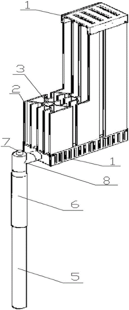
Figure 1 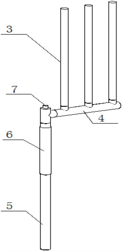
Figure 2 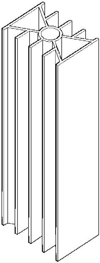
Figure 3
Abstract
Description
technical field
[0001] The invention relates to a heating device, in particular to an underground gravity heat pipe direct heating device. Background technique
[0002] At present, the existing heating technology still mainly relies on conventional energy, but the consumption of conventional energy has aggravated environmental pollution and caused many problems. Therefore, rational use of new energy such as geothermal energy is an inevitable choice.
[0003] At present, there is no technology of using buried gravity heat pipes to directly heat radiators, but using buried gravity heat pipes to directly heat radiators for low-temperature heating rooms that do not require high room temperature can improve the utilization rate of geothermal energy and reduce the consumption of conventional energy. Consumption, in line with the requirements of social energy-saving development.
[0004] As a high-efficiency heat exchange unit, the buried gravity heat pipe has the advantages of o...
Examples
Embodiment 1
[0021] Such as figure 1 As shown, the heating device includes a heat absorbing section 5 of a gravity heat pipe, an adiabatic section 6 of a gravity heat pipe, a decorative protective cover 1, an aluminum airfoil heat sink 2, a cooling branch pipe 3, a horizontal main pipe 4 and a liquid filling port 7; The decorative protective cover 1 is screwed on the aluminum airfoil heat sink 2; the aluminum airfoil heat sink 2 is connected to the heat dissipation branch pipe 3 by expansion; the heat dissipation branch pipe 3 and the horizontal main pipe 4 are connected by welding; the horizontal main pipe 4 is connected by The tee 8 is connected to the heat insulation section 6 of the gravity heat pipe; the liquid filling port 7 is welded to the end of the tee 8 which is not connected. The heat-absorbing section 5 and the heat-insulating section 6 are vertically placed in the soil, wherein the heat-absorbing section 5 is placed at a depth of 10m-15m in the soil constant temperature layer...
Embodiment 2
[0023] Such as Figure 4 As shown, in this embodiment, the decorative protective cover 1 is removed, and a pair of face-to-face heat dissipation aluminum plates 9 are used to replace the aluminum airfoil heat sink 2, and a strip-shaped slot is left on the heat dissipation plate, and the gravity heat pipe buried in the ground The heat dissipation branch pipe 3 is embedded in the groove, and the heat dissipation plates 8 arranged face to face are fixed by screw connection. Other positions are similar to Example 1.