
A reference signal transmission device, method and system
A reference signal and quasi-reference signal technology, applied in multi-frequency code systems and other directions, can solve problems such as lack of synchronization, frequency deviation, and inability to communicate normally, saving physical resources and improving data transmission efficiency.
Patent Information
- Authority / Receiving Office
- CN · China
- Patent Type
- Patents(China)
- Current Assignee / Owner
- Publication Date
- 2020-06-26
Smart Images

Figure 1 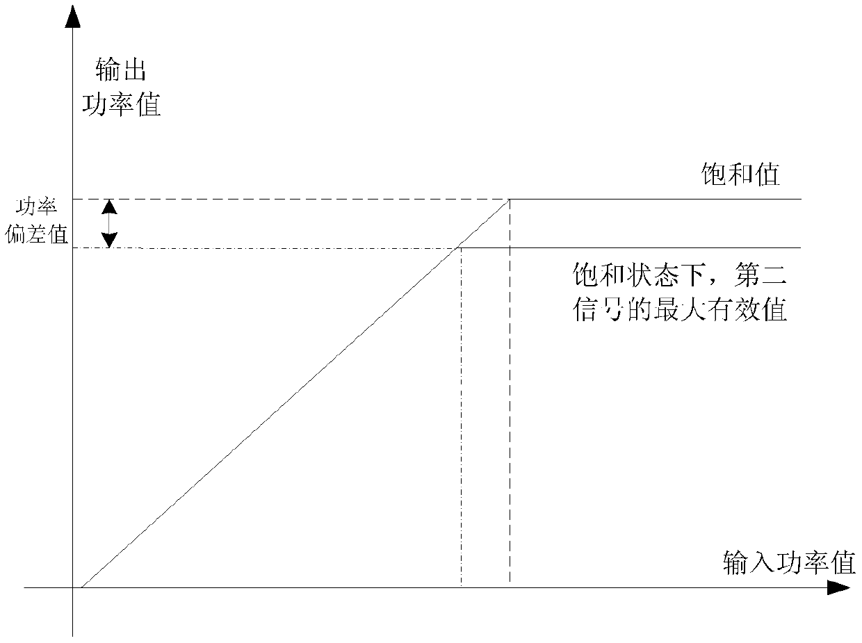
Figure 2 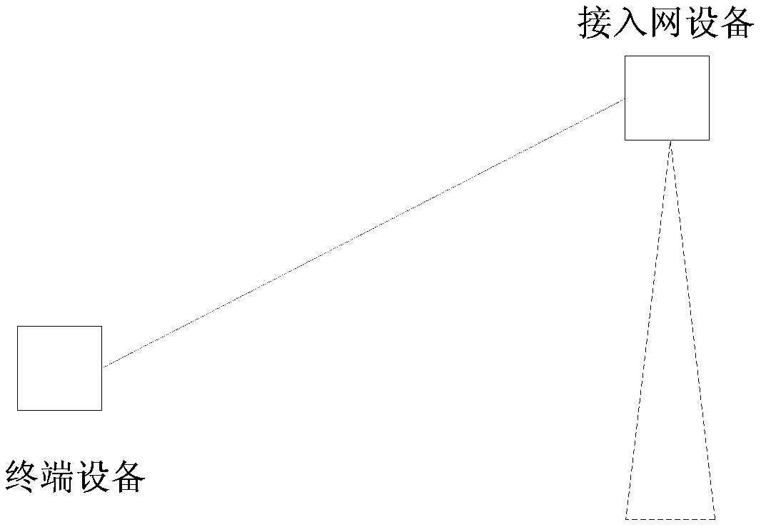
Figure 3
Abstract
Description
technical field
[0001] The present application relates to the technical field of wireless communication, and in particular to a reference signal transmission device, method and system. Background technique
[0002] In a wireless communication system, a reference signal (Reference Signal, RS) is sent by a reference signal transmitting device to a reference signal receiving device, which can be used for channel estimation, signal demodulation, automatic gain control (Automatic GainControl, AGC), signal quality measurement, Positioning, as well as channel detection, positioning, etc., the receiving device of the reference signal knows the reference signal to be received in advance, so that the purpose of signal processing such as channel estimation of the receiving device can be achieved.
[0003] In a wireless communication system, a prerequisite for normal communication between devices is that these devices are in a synchronized state. However, various reasons may lead to in...
Examples
Embodiment 1
[0291] Such as Figure 5 As shown, the wireless communication system provided in Embodiment 1 includes: a reference signal sending device 501 and a reference signal receiving device 502. For the sake of brevity, the reference signal sending device 501 is referred to as "transmitting device 501" below, and the reference signal The receiving device 502 is referred to as "receiving device 502".
[0292] Wherein, the sending device 501 is configured to determine a reference signal, and send the determined reference signal;
[0293] The receiving device 502 is configured to receive a reference signal and process the received reference signal, such as performing channel estimation, signal demodulation, AGC, wireless measurement, and channel detection based on the received reference signal.
[0294] Figure 6 An optional process for generating and sending a reference signal by the sending device 501 is shown.
[0295] Such as Figure 6 As shown, the process may include the follow...
Embodiment 2
[0312] In Embodiment 2 and Embodiment 3, the reference signal may be the aforementioned first type of reference signal, and may be applicable to high-speed moving scenarios and / or scenarios with large frequency deviation values.
[0313] Wherein, optionally, in each subframe occupied by the reference signal, the reference signal occupies at least four symbols, and there are two symbols in the at least four symbols, and the intersymbol interval between the two existing symbols is not greater than two symbols .
[0314] Among them, the reference signal occupies at least four symbols in each occupied subframe, which can ensure that the receiving device of the reference signal can obtain enough reference signal resources for frequency offset estimation, and can also ensure that the communication device moves at a high speed and the channel fades quickly. In serious cases, more reference signals can be obtained per unit time, so that the result of channel estimation based on the re...
Embodiment 3
[0384] In the third embodiment, the reference signal is mapped into a synchronous subframe. The synchronization subframe includes a synchronization signal, and the synchronization signal is used for synchronization between communication devices.
[0385] Here, the synchronous subframe takes the synchronous subframe in the current D2D system as an example. Wherein, PD2DSS is, SD2DSS is, in the subframe, the last symbol may be GAP, or the subframe does not include GAP. The reference signal takes DMRS as an example.
[0386] Figure 9A It shows the mapping manner of the current DMRS in the synchronous subframe of the D2D system. The DMRS occupies symbols 3 of the first time slot and the second time slot respectively. The symbols between the symbols occupied by the two DMRSs and the symbol 0 of the first time slot are used for sending PSBCH signals. Figure 9A The shown time-frequency resource occupies a subframe of 1 ms in the time domain, and occupies 6 PRBs in the frequenc...