
Small fruit automatic loading device
An automatic feeding and fruit technology, applied in the direction of transportation and packaging, conveyors, rollers, etc., can solve the problems of inability to realize accurate equal interval feeding, unable to realize equal interval automatic feeding, easy congestion and material jams, etc. Achieve the effect of simple structure, easy control and fast response time
Patent Information
- Authority / Receiving Office
- CN · China
- Current Assignee / Owner
- Publication Date
- 2018-07-24
- Estimated Expiration
- Not applicable · inactive patent
Smart Images
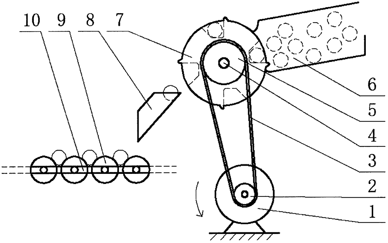
Figure 1 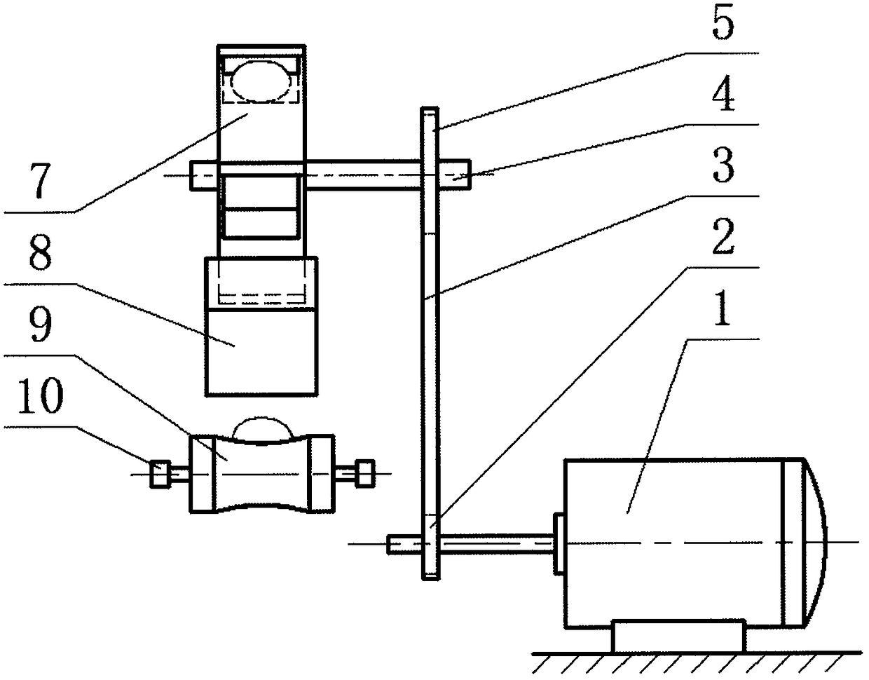
Figure 2
Abstract
Description
technical field
[0001] The invention relates to an automatic feeding device for a small fruit classifier. Background technique
[0002] The annual output of small fruits and vegetables in my country is huge, such as red dates, chestnuts, hawthorns, walnuts, small potatoes and garlic, etc. With the development of mechanization and automation technology in various industries, in order to increase the market value of agricultural products, various sorting machines Have appeared. The feeding device is an important part of the sorting machine. At present, there are many types of such devices, such as conveyor belt feeding device, vibrating feeding device and chute feeding device. Although the conveyor belt type feeding device is relatively simple to control, it is mostly integrated with the whole machine, the structure is more complicated, and the overall size is larger; the vibration type feeding device can solve the problem of material jamming well, but it cannot realize accura...
Examples
Embodiment Construction
[0013] The present invention will be described in detail below in conjunction with the accompanying drawings.
[0014] Such as figure 1 and figure 2 , a small fruit automatic feeding device, including a motor 1, a driving pulley 2, a timing belt 3, a transmission shaft 4, a driven pulley 5, a storage box 6, a feeding wheel 7, a guide channel 8, and a roller 9 and conveyor chain 10.
[0015] The motor 1 is energized to drive the driving pulley 2 installed on the output shaft to rotate, and the two ends of the synchronous belt 3 are meshed with the driving pulley 2 and the driven pulley 5 respectively. The driving pulley 5 rotates; the driven pulley 5 is installed on the transmission shaft 4, and the driven pulley 5 drives the transmission shaft 4 to rotate, and the feeding wheel 7 and the driven pulley 5 are installed on the transmission shaft 4 at a certain interval, so The above material wheel 7 just keeps rotating at the same speed with the driven pulley 5; It will rota...