
Multiphase filtering-based continuous wave radar receiver
A polyphase filtering and wave radar technology, which is applied in radio wave measurement systems, measurement devices, instruments, etc., can solve the problem of increasing the number of hardware and interfaces of the receiving circuit, which is not conducive to the miniaturized design of multi-channel receiving, and has high requirements for calibration networks. problem, to achieve the effect of facilitating low-noise design, realizing image frequency suppression, and improving signal-to-noise ratio
Patent Information
- Authority / Receiving Office
- CN · China
- Patent Type
- Applications(China)
- Current Assignee / Owner
- Publication Date
- 2018-07-31
- Estimated Expiration
- Not applicable · inactive patent
Smart Images
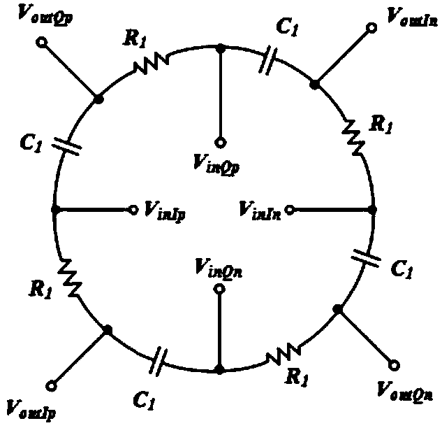
Figure 1 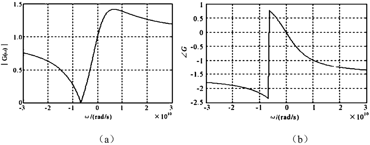
Figure 2 
Figure 3
Abstract
Description
technical field
[0001] The invention belongs to the field of radar receiver system design, and specifically relates to a zero-IF continuous wave radar receiver, which is mainly used in continuous wave radar systems to suppress image signals and reduce aliasing effects introduced by upper and lower sidebands of baseband signals. It is suitable for various continuous wave transceiver systems and has good versatility. Background technique
[0002] In the traditional superheterodyne receiver system, the I and Q two-way orthogonal intermediate frequency signals output by the down-conversion of the receiver can be synthesized by a 90° electric bridge to suppress the image frequency signal. In the radar system of the continuous wave system, the zero-IF signal is obtained by down-conversion, and the system image signal is the useful signal itself, which cannot eliminate the problems caused by image suppression. The upper and lower sidebands of the obtained baseband signal will be su...
Examples
Embodiment Construction
[0024] Now in conjunction with embodiment, accompanying drawing, the present invention will be further described:
[0025] The passive polyphase filter is derived from the RC-CR phase-shifting network, a passive linear network composed of resistors and capacitors, such as figure 1 shown. The input signals in the figure are quadrature differential signals, and they are orthogonal to each other. The transmission network can generate output signals with equal amplitude and phase quadrature at frequency ω=1 / (RC).
[0026] It can be concluded that the frequency transfer function of the first-order RC polyphase network is:
[0027] where h 1 =1 / (1+jωR 1 C 1 ), h' 1 =-jωR 1 C 1 / (1+jωR 1 C 1 ), its amplitude-frequency response: G 1 =(1+ωR 1 C 1 ) / (1+jωR 1 C 1 ). The RC network has Hilbert transform network characteristics, ω=-1 / (R 1 C 1 ) has a zero at ω=1 / (R 1 C 1 ) has a pole, the curve such as figure 2 shown.
[0028] According to the Hilbert transform tran...