
Horizontal Throat Block Driving Device of Semi-flexible Nozzle Guide Rail in Continuous Transonic Wind Tunnel
A driving device and transonic technology, which is applied in the field of semi-flexible nozzle guide rail horizontal throat block driving device, can solve the problems of not being able to provide the throat block and inconvenience, etc., and achieve powerful posture adjustment capabilities, large driving force, and reduced The effect of machining error and installation error
Patent Information
- Authority / Receiving Office
- CN · China
- Patent Type
- Patents(China)
- Current Assignee / Owner
- Publication Date
- 2021-01-26
Smart Images
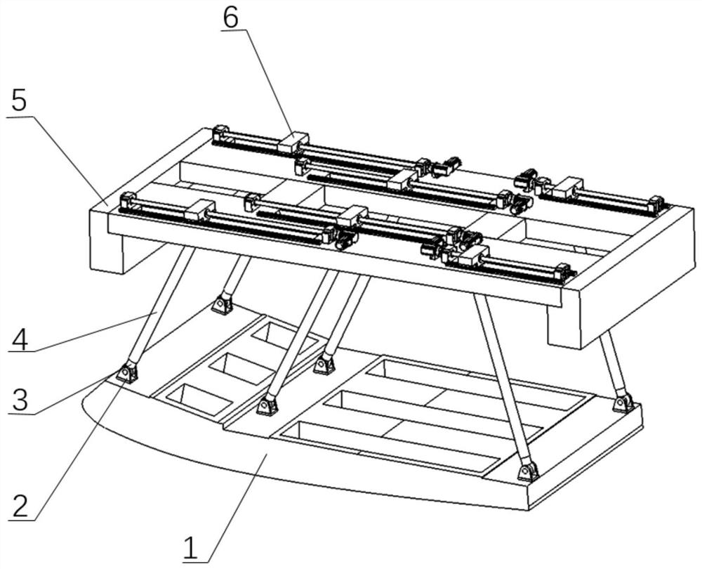
Figure 1 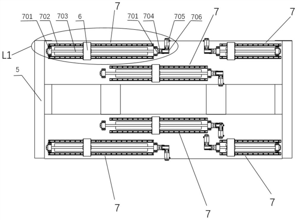
Figure 2 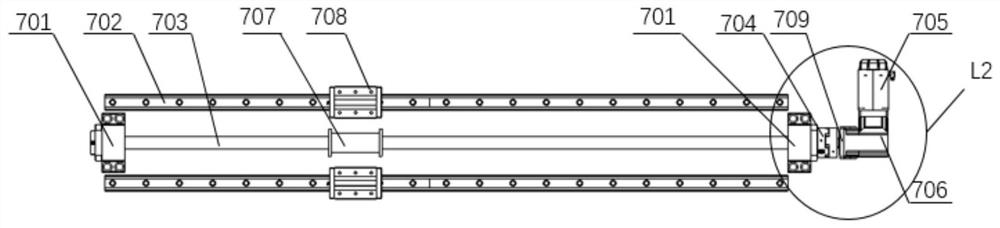
Figure 3
Abstract
Description
technical field
[0001] The invention relates to a continuous transonic wind tunnel nozzle section semi-flexible wall guide rail horizontal throat block drive device, which belongs to the field of special equipment for wind tunnel testing, and is a semi-flexible device for precise adjustment of different Mach numbers of the nozzle section in the wind tunnel. Horizontal throat block drive for wall nozzle guides. Background technique
[0002] The wind tunnel is an important test device used to verify whether the aerodynamic shape of various types of aerospace vehicles and high-speed EMUs is reasonable. Its main principle is to simulate the external gas flow field characteristics (Mach number, Reynolds number, etc.) number, Prandtl number, etc.), and make a series of evaluations on the measured parameters of the tested object in the simulated flow field, so as to realize the prediction of its characteristics under real working conditions. Wind tunnels can be divided into subson...
Examples
Embodiment 1
[0028]The support platform (5) is a flat plate with slots placed horizontally, used for installing and precisely positioning the guide rail (702), and can fully bear the force of the guide rail (702) on it during work. Good rigidity is ensured by designing its structure, which will ensure the pose forming accuracy of the final throat block (1). Several drive units (7) are housed on the support platform (5), and each drive unit (7) includes: a servo motor (705) is connected with a right-angle reducer (706) to reduce the output speed of the motor, and the servo motor (705 ) and the reducer (706) are horizontally installed on the support platform (5) through the reducer support (709); The leading screw (703) is installed on the top of the support platform (5) by the leading screw support (701), the output of the reducer (706) drives the leading screw (703) to rotate through the shaft coupling (704), and the leading screw nut (707 ) converts the rotation of the leading screw (703...
Embodiment 2
[0030] The main structure of this embodiment is the same as that of Embodiment 1. Furthermore, in addition to bearing the weight of each component, the semi-flexible throat block of the nozzle section of the large-scale continuous transonic wind tunnel also needs to consider the complex and variable aerodynamic load. It is necessary to judge the layout of the guide rail slider according to the force of the specific mechanism. It is a double guide rail double slider arrangement or a multi guide rail multi slider arrangement, so as to ensure that the force is within the bearing range of the guide rail slider and make the guide rail slider normal. operation, and to ensure that it has a certain service life.
Embodiment 3
[0032] The main structure of this embodiment is the same as that of Embodiment 1. Furthermore, since the semi-flexible guide rail horizontal throat block driving device of the continuous transonic wind tunnel nozzle section will be subjected to lateral force, the guide rail horizontal throat block driving device is designed as A six-degree-of-freedom mechanism is used to obtain the ability to actively resist lateral forces, so the rotating hinge can choose a spherical hinge. However, since the displacement of the throat block in the longitudinal direction is very small, the space pose of the throat block is less than 5° at the lateral inclination angle, and since the joint bearing can rotate in three directions at a small angle, the joint bearing can also be used for the rotary hinge.