
Reverse-circulation pneumatic impact down-the-hole hammer
A technology of down-the-hole hammer and reverse circulation, which is applied to the driving device for drilling, drilling equipment, earth-moving drilling and other directions in the wellbore, can solve the problems of lack of rock-breaking drilling speed, shortened tool life, reliability impact, etc. Achieve the effect of improving reliability and service life, improving purity, and increasing speed
Patent Information
- Authority / Receiving Office
- CN · China
- Patent Type
- Applications(China)
- Current Assignee / Owner
- Publication Date
- 2018-09-07
Smart Images
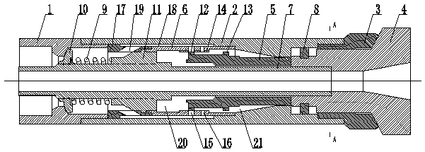
Figure 1 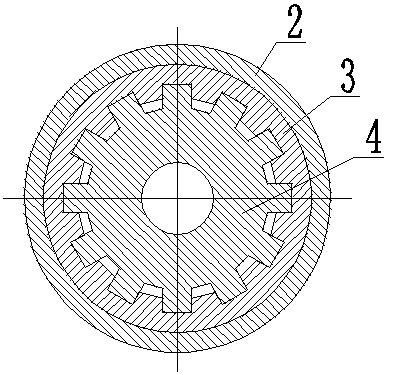
Figure 2 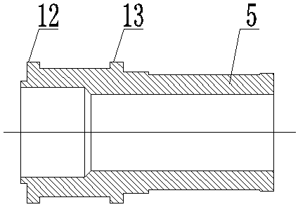
Figure 3
Abstract
Description
technical field
[0001] The invention relates to an impact down-the-hole hammer, in particular to a reverse-circulation pneumatic impact down-the-hole hammer. Background technique
[0002] In the process of my country's current economic construction, the reverse circulation impact DTH hammer plays an increasingly important role in geotechnical drilling engineering. It is widely used in water supply, mining, municipal, environment, transportation and construction. Greatly improve drilling efficiency, reduce construction costs, and ensure project quality. Its economic benefits are very significant, and it has been highly valued by the drilling industry at home and abroad. Hammer works, using the reciprocating impact of the impactor on the drill bit to achieve the purpose of breaking the rock, and the broken rock is carried to the ground with the exhaust gas discharged after the DTH hammer works, so as to achieve the purpose of hole cleaning and slag discharge. However, due to The...
Examples
Embodiment Construction
[0023] The reverse cycle pneumatic impact down-the-hole hammer is composed of an upper joint 1, a housing 2, a spline sleeve 3, a drill bit 4, a hammer 5 and a cylinder 6. One end of the housing 2 is threaded with the upper joint 1, and the other end of the housing 2 A spline sleeve 3 is mounted on one end thread, and a drill bit 4 is slidably installed in the spline sleeve 3 through a keyway; a C-shaped snap ring 8 is fixedly installed on the drill bit 4 . The purpose of the C-type snap ring 8 is to carry out intermittent contact with the end face of the spline sleeve 3 to realize axial positioning of the drill bit 4, so as to prevent the drill bit 4 from falling to the bottom of the well when pulling out the drill in the working process.
[0024] A core tube 7 is installed in the housing 2 on one side of the drill bit 4 , and the core tube 7 is a diameter-reducing body, and a diameter-reducing boss 11 is arranged on the circumference of the core tube 7 . A check valve 10 is ...