
A simulation test bench for shield machine cutter head and its use method
A technology for simulating test benches and shield machines, which is applied in the testing of mechanical components, testing of machine/structural components, earthwork drilling and mining, etc., to achieve the effect of meeting strength requirements, reducing risks and costs, and being easy to process
Patent Information
- Authority / Receiving Office
- CN · China
- Patent Type
- Patents(China)
- Current Assignee / Owner
- Publication Date
- 2019-11-05
- Estimated Expiration
- Not applicable · inactive patent
Smart Images
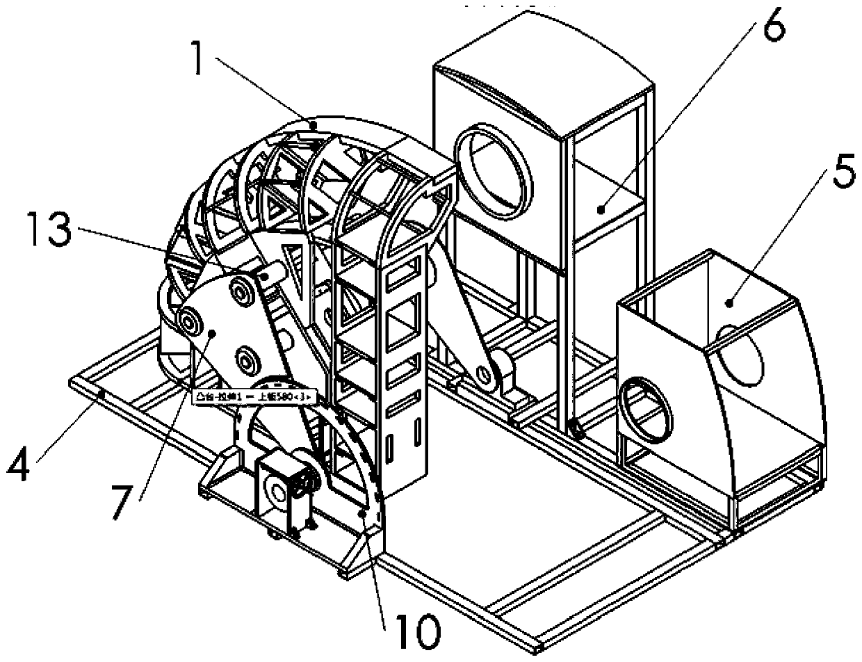
Figure 1 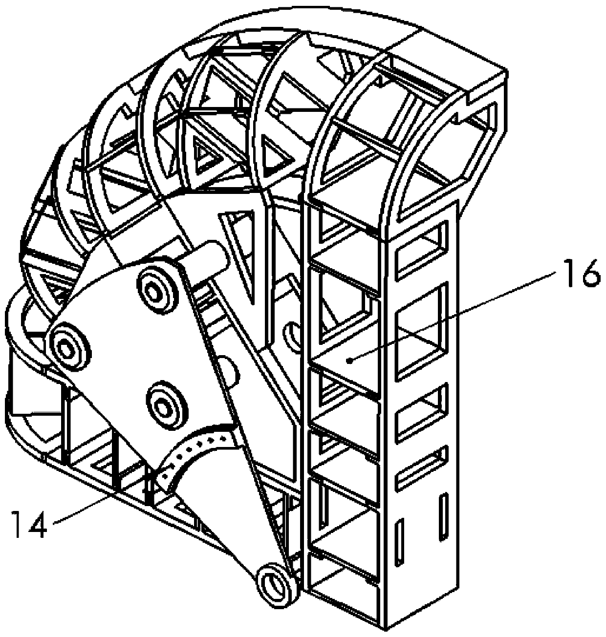
Figure 2 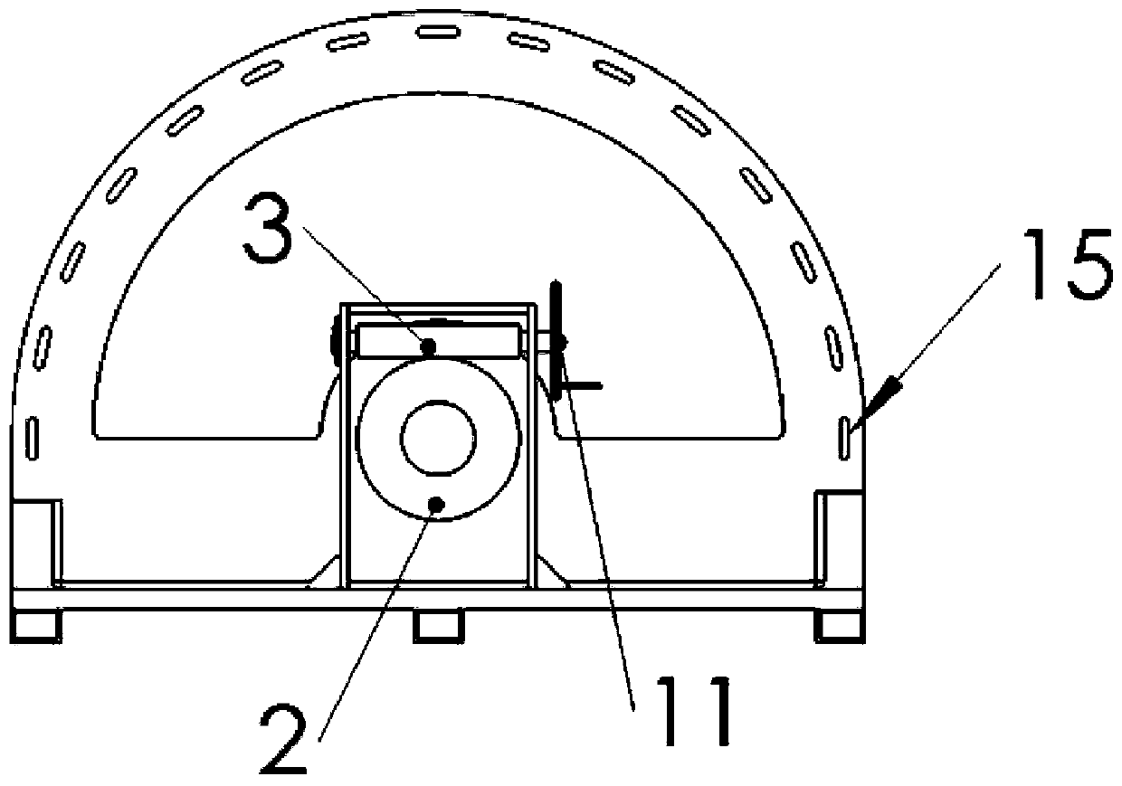
Figure 3
Abstract
Description
technical field
[0001] The invention relates to a construction machinery test device, in particular to a simulation test bench for a shield machine cutterhead and a method for using the same. Background technique
[0002] At present, there are two ways to change the tool of the slurry balance shield machine, normal pressure tool change and pressure tool change. , the conditions for manual tool change under pressure are harsh. Operators enter the mud tank under pressure to inspect and replace worn hobs. They need to withstand high pressure and high humidity, and are prone to accidents and life-threatening. In the case of immature technology of tool changing robots, it is not convenient to carry out tool changing experiments in actual working environments.
[0003] The disc-shaped hob of the slurry balance shield machine needs to be replaced many times during the entire project period, and each time the hob is replaced, the angular position of the hob that needs to be replac...
Examples
Embodiment Construction
[0031] The present invention will be further elaborated below in conjunction with the accompanying drawings of the description.
[0032] Such as Figure 1~4 As shown, a simulation test bench of a shield machine cutter head in the present invention includes: a cutter head 1, a worm gear structure, a base 4, a knife storage bin 5, and a manipulator installation bin 6, wherein the cutter head 1 is installed by rotating the mounting plate On the base, the knife storage bin 5 and the manipulator installation bin 6 are all installed on the base 4, and the worm gear structure is installed on the side of the base 4 and the side of the cutter head 1. In the worm gear structure, the shaft of the worm wheel 2 and the cutter head 1 The shafts are coaxially fixed together, and the worm gear structure is provided with a hand wheel 11, and the hand wheel 11 is axially fixedly connected with the worm 3 in the worm gear structure.
[0033] Such as figure 2 As shown, the cutter head is a qua...