
Polyurethane spinning method
A polyurethane and spinning technology, which is applied in the field of gas treatment equipment, can solve the problems of impurity filtration, restriction, and inability to use tail gas power, etc., and achieves the effect of improving purification efficiency and purification capacity.
Patent Information
- Authority / Receiving Office
- CN · China
- Current Assignee / Owner
- Publication Date
- 2018-11-30
Smart Images
Figure 1 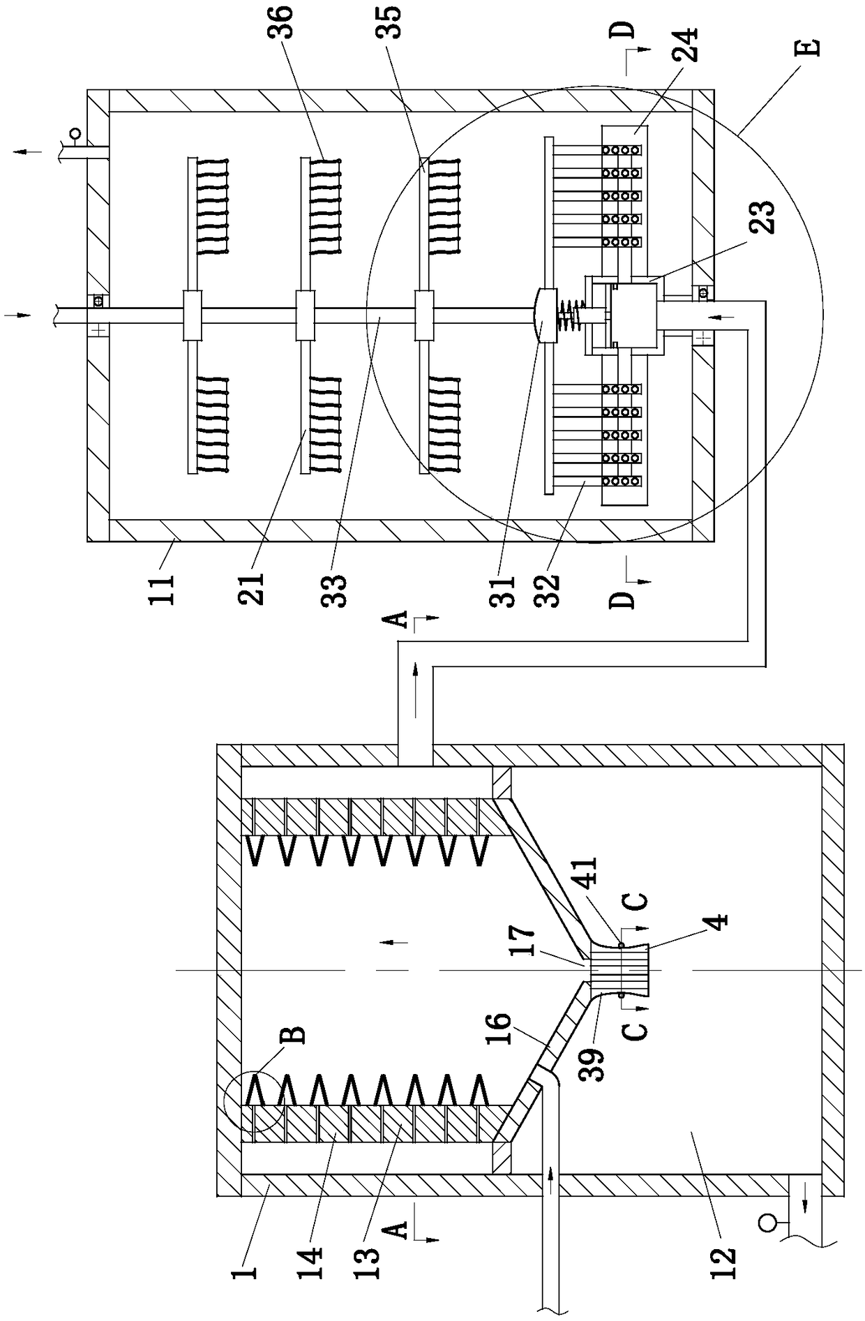
Figure 2 
Figure 3
Abstract
Description
technical field
[0001] The invention belongs to the field of gas treatment equipment, in particular to a polyurethane spinning method. Background technique
[0002] Polyurethane is mainly formed by the polyaddition reaction of diisocyanate or polyisocyanate with dihydroxy or polyhydroxy compounds. It has excellent properties such as high elasticity, wear resistance, low temperature resistance, solvent resistance and aging resistance, so it is widely used in various fields of national economy. A large amount of volatile organic gases are produced in the polyurethane spinning process, which poses a threat to the life and health of the staff; among them, volatile organic gases refer to VOCs waste gas.
[0003] VOCs waste gas is a common industrial waste gas in the chemical industry. It has complex components and contains a large amount of organic substances such as hydrocarbons, aldehydes, chlorinated hydrocarbons, etc. Most of the components are carcinogenic pollutants. If th...
Examples
Embodiment approach
[0045] As an embodiment of the present invention, the air flotation module 2 includes a hollow shaft 22, an air storage tank 23, a rotating plate 24 and a shielding unit 25; the hollow shaft 22 is rotatably connected to the conduit through a bearing; the upper end of the hollow shaft 22 It is fixedly connected with the gas storage tank 23, and the hollow shaft 22 is used to transport the tail gas in the conduit to the gas storage tank 23; the number of the rotating plates 24 is multiple, and the multiple rotating plates 24 are evenly installed in a circular arrangement. The side wall outer surface of the gas tank 23; the side surface of the rotating plate 24 in contact with the gas tank 23, the surface is provided with a No. 1 gas storage tank 26; the top surface of the rotating plate 24 is provided with a No. 2 gas storage tank 27, The side surface of the rotating plate 24 is provided with an air injection hole 28 communicating with the No. 2 air storage tank 27; the air injec...