
A microstrip bandpass filter
A band-pass filter and filter technology, applied in the field of filters, can solve the problems of large filter volume, unfavorable integration, affecting filter suppression, etc., and achieve low insertion loss, miniaturization, and large out-of-band suppression. Effect
Patent Information
- Authority / Receiving Office
- CN · China
- Patent Type
- Applications(China)
- Current Assignee / Owner
- Publication Date
- 2018-12-25
Smart Images
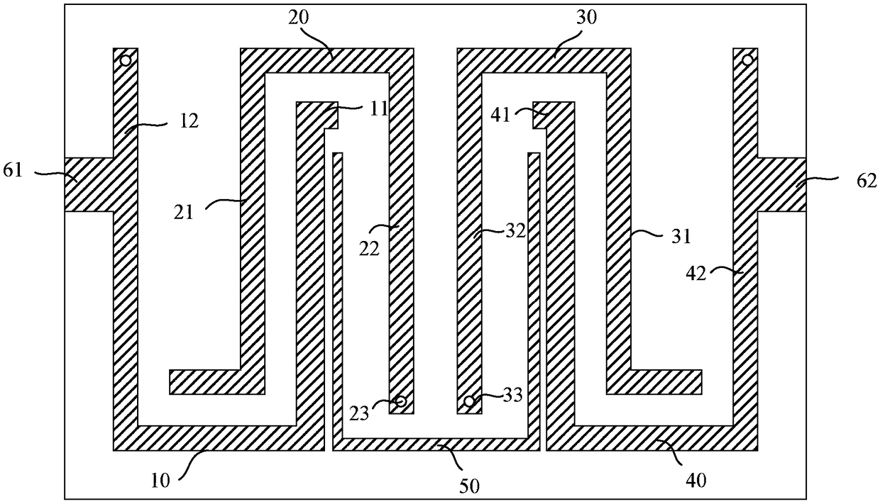
Figure 1 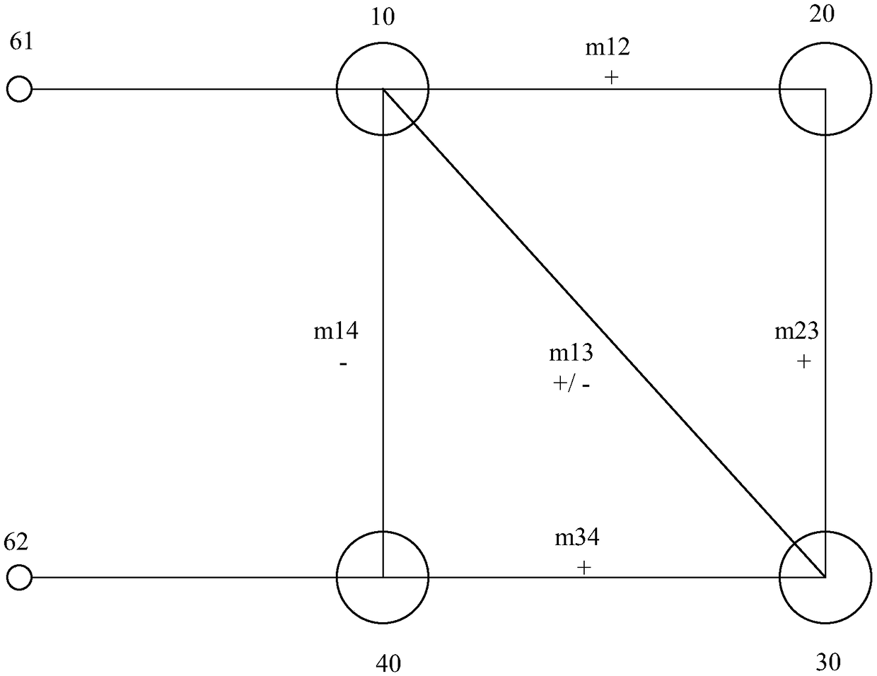
Figure 2 
Figure 3
Abstract
Description
technical field
[0001] The invention relates to the field of filters, in particular to a microstrip bandpass filter. Background technique
[0002] Microwave filter is an indispensable part of modern microwave relay communication, satellite communication, wireless communication and electronic countermeasures and other systems, and it is also the most important and most technical microwave passive device. Among them, the band-pass filter is one of the most important components in the circuit system, and its performance determines the working quality of the system to a large extent. Band-pass filters mainly work in the radio frequency front-end of communication systems, and are used to pass useful signals in a certain frequency range with low loss, while attenuating frequency components in other frequency ranges to a very low level.
[0003] However, with the rapid development of modern communication requirements, the available spectrum resources are increasingly tight, so the...
Examples
Embodiment 1
[0058] figure 1 A schematic structural diagram of the first embodiment of the present invention is presented in figure 1 As shown, the opening directions of the first resonance unit 10 and the fourth resonance unit 20 are the same; the opening directions of the second resonance unit 20 and the third resonance unit 30 are the same and opposite to the opening direction of the first resonance unit 10 .
[0059] The short-circuit point 23 of the second resonance arm 22 of the second resonance unit 20 is adjacent to the short-circuit point 33 of the second resonance arm 32 of the third resonance unit 30 .
[0060] Wherein, both ends of the cross-coupled microstrip line 50 are respectively coupled with the first resonance unit 10 and the fourth resonance unit 40, and both ends of the cross-coupled microstrip line 50 are open circuits, so as to generate two Transmit zero.
[0061] Specifically, both ends of the cross-coupled microstrip line 50 are respectively coupled with the firs...
Embodiment 2
[0064] Figure 4 A schematic structural diagram of a second embodiment of the present invention is presented in Figure 4 As shown, the opening directions of the first resonance unit 10 and the third resonance unit 30 are the same; the opening directions of the second resonance unit 20 and the fourth resonance unit 20 are the same and opposite to the opening direction of the first resonance unit 10 .
[0065] The short-circuit point 23 of the second resonance arm 22 of the second resonance unit 20 and the short-circuit point 33 of the second resonance arm 32 of the third resonance unit 30 are away from each other.
[0066] The two ends of the cross-coupled microstrip line 50 are respectively coupled with the first resonance unit 10 and the third resonance unit 30, and both ends of the cross-coupled microstrip line 50 are open circuits to generate two transmission zeros at low frequencies.
[0067] Specifically, both ends of the cross-coupled microstrip line 50 are respectivel...
Embodiment 3
[0070] Figure 7 A schematic structural diagram of a second embodiment of the present invention is presented in Figure 7 As shown, the opening directions of the first resonance unit 10 and the third resonance unit 30 are the same; the opening directions of the second resonance unit 20 and the fourth resonance unit 20 are the same and opposite to the opening direction of the first resonance unit 10 .
[0071] The short-circuit point 23 of the second resonance arm 22 of the second resonance unit 20 and the short-circuit point 33 of the second resonance arm 32 of the third resonance unit 30 are away from each other.
[0072] Wherein, both ends of the cross-coupled microstrip line 50 are respectively coupled with the second resonance unit 20 and the fourth resonance unit 40, and both ends of the cross-coupled microstrip line 50 are short-circuited to generate two transmission zeros at high frequencies .
[0073] Specifically, both ends of the cross-coupled microstrip line 50 ar...