
Unpowered ventilation device and tunnel
A technology for power ventilation and ventilation pipes, which is applied in the direction of pump devices, mine/tunnel ventilation, engines, etc. It can solve problems such as weak ventilation capacity, high power consumption, and inability to meet the ventilation requirements of the tunnel body, and achieve stable fan direction , The effect of gas flow stability
Patent Information
- Authority / Receiving Office
- CN · China
- Patent Type
- Applications(China)
- Current Assignee / Owner
- Publication Date
- 2019-04-16
Smart Images
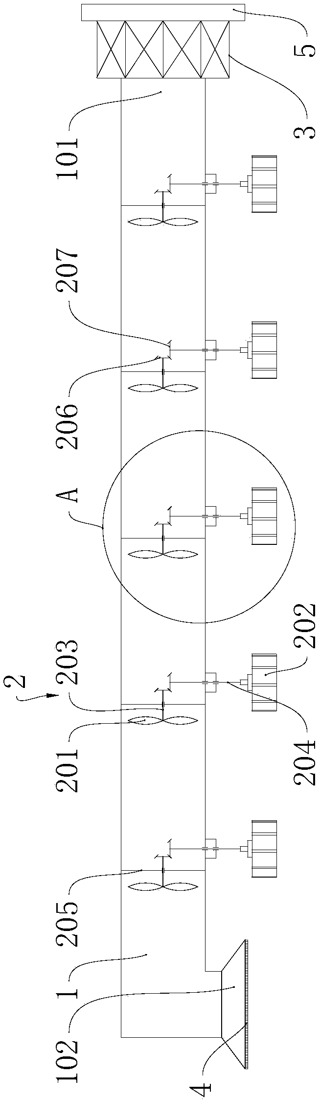
Figure 1 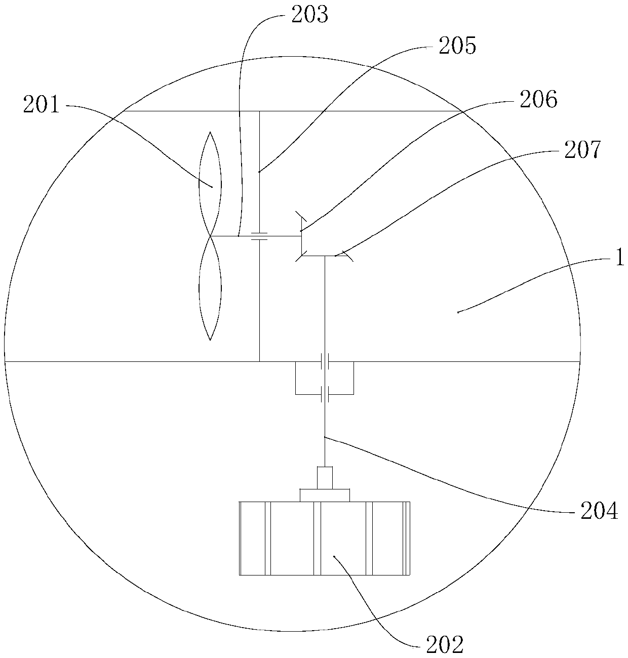
Figure 2 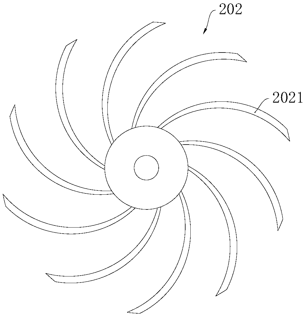
Figure 3
Abstract
Description
technical field
[0001] The invention relates to the technical field of ventilation in mines or tunnels, in particular to a non-powered ventilation device and a tunnel. Background technique
[0002] The air retention in the tunnel body will seriously affect the air quality in the inner cavity of the tunnel body, which is unfavorable to the health of passers-by, especially for some narrow and long tunnel bodies, the deeper the inner cavity of the tunnel body is, the more air in the inner cavity of the tunnel body will be. The less gas exchange there is between the air and the atmosphere outside the tunnel body, resulting in poorer air quality in the inner cavity of the tunnel body.
[0003] In order to solve the above problems, various ventilation devices have been proposed in the prior art. However, most of the existing ventilation devices rely on external electric power to drive fans to ventilate the tunnel body. The cost of transportation operation is poor, and the economy...
Examples
Embodiment 1
[0043] Please refer to Figure 1 to Figure 4 The tunnel provided by this embodiment includes a tunnel body and the aforementioned unpowered ventilation device, the ventilation duct 1 is arranged along the extension direction of the tunnel body, the first tuyere 101 is located outside the tunnel body, and the second tuyere 102 is located in the inner cavity of the tunnel body, The vortex impeller 202 is located in the inner cavity of the tunnel body, and the rotation axis of the vortex impeller 202 is perpendicular to the extending direction of the tunnel body.
[0044]Because the tunnel body 6 is generally a long and narrow space, the closer to the exit of the tunnel body 6 in the long and narrow space of the tunnel body 6, the more the gas exchanges with the gas outside the tunnel body 6, and the farther away the gas at the position of the tunnel body 6 exit is. The less the exchange with the gas outside the tunnel body 6; the worse the gas quality is at the position farther ...
Embodiment 2
[0050] The tunnel provided by this embodiment includes a tunnel body and at least two sets of the aforementioned non-powered ventilation devices. Each ventilation duct 1 is arranged along the extension direction of the tunnel body. External environment; each vortex impeller 202 is located in the inner cavity of the tunnel main body, and the rotation axis of each vortex impeller 202 is perpendicular to the extension direction of the tunnel main body; in some non-powered ventilation devices, the rotating fan 201 is from the outside of the tunnel main body to the inside of the tunnel main body The direction of the cavity; in another part of the non-powered ventilation device, the rotating fan 201 fans the direction from the inner cavity of the tunnel body to the outside of the tunnel body. Due to the adoption of the aforementioned unpowered ventilation device, the vortex impeller 202 is used to rotate with the airflow outside the ventilation duct 1, so that even if the airflow dir...