
Pole-attached coil of DC motor and its winding method
A DC motor and motor winding technology, which is applied in the manufacture of motor generators, electromechanical devices, electrical components, etc., can solve the problems of easy damage to the insulation of inter-turn intersections, short circuits between turns, and low winding density of turns, so as to facilitate wiring and The effect of installation operation, improving power density, and increasing the number of winding turns
Patent Information
- Authority / Receiving Office
- CN · China
- Patent Type
- Patents(China)
- Current Assignee / Owner
- Publication Date
- 2019-06-25
Smart Images
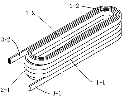
Figure 1 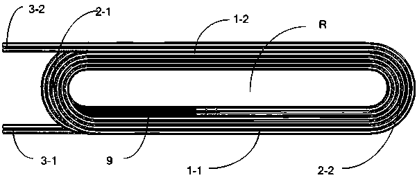
Figure 2 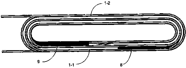
Figure 3
Abstract
Description
technical field
[0001] The invention relates to the technical field of motors, in particular to a polarized coil of a DC motor and a winding method thereof. Background technique
[0002] As an important part of the DC motor stator, the attached pole coil is mainly used to improve the commutation performance of the motor, also known as the commutation pole coil.
[0003] The pole-attached coil of a DC motor is a concentrated winding coil. For a multi-layer multi-turn coil, a formed winding wire with an insulating layer is usually used to wind it on a mold and then put it into the pole core of the motor. The conventional practice is to wind in one direction, and the lead-out wires at the beginning and end are drawn from the inner and outer layers of the coil respectively; the coil winding process is usually a direct transition transfer between turns and layers, and because the width of the DC motor’s attached pole core is small, Turns and layers cannot be transitioned at the ...
Examples
Embodiment 1
[0058] see Figure 1 to Figure 9 As shown, this embodiment provides a polarized coil of a DC motor, comprising: an elliptical ring body formed by winding one or more parallel motor winding wires; wire 3-1, and the second lead-out wire 3-2 arranged at the end of the motor winding wire. In this embodiment, the structure of two parallel motor winding wires is taken as an example.
[0059] Specifically, the elliptical ring body includes a forward winding coil group and a reverse winding coil group formed by integral winding; the forward winding coil group and the reverse winding coil group are wound to form a relatively distributed first straight line portion 1- 1 and the second straight part 1-2, and the first arc part 2-1 and the second arc part 2 which are connected to the first straight part 1-1 and the second straight part 1-2 and are relatively distributed -2; the first lead-out line 3-1 is located at the outer end of the elliptical inner hole R of the forward winding coil...
Embodiment approach
[0061] The motor winding wire of this embodiment is preferably a winding wire with its own insulating layer; in an optional embodiment, the winding wire is a double glass fiber-wrapped film-wrapped copper flat wire or a single glass fiber-wrapped film-wrapped copper flat wire. There is no absolute limit to the specific model of the specific double glass fiber wrapped film wrapped copper flat wire or single glass fiber wrapped film wrapped copper flat wire.
[0062] With reference to the drawings of the embodiment, this embodiment takes a pole-attached coil with a three-layer structure as an example, the number of layers of the forward winding coil group is three layers, and the number of layers of the reverse winding coil group is three layers. The first lead-out line 3-1 protrudes from the first straight line 1-1 to the direction in which the first arc-shaped portion 2-1 extends; the second lead-out line 3-2 extends from the second straight line 1-2 to the first arc The direc...
Embodiment 2
[0070] This embodiment provides a method for winding an attached pole coil of a DC motor, which specifically includes:
[0071] Step S1: Reserve a section of motor winding wire at one end of one or more parallel motor winding wires to form the reserved motor winding wire 11; the length of the reserved motor winding wire is equal to or greater than that of the reverse winding coil group The sum of the length of the required motor winding wire and the length of the first lead wire 3-1;
[0072] Step S2: Three layers of motor winding wires other than the reserved motor winding wires in the motor winding wires in step S1 are forward wound to form a forward winding coil group; at the end of the motor winding wire of the forward winding coil group, The second lead-out line 3-2;
[0073] Step S3: Reversely wind three layers of the reserved motor winding wire 11 in step S1 to form a reverse winding group; the reverse winding direction of the reverse winding group is the same as that ...