
Control circuit and method for discharge circuit, chip and driving system and method
A technology of bleeder circuit and control circuit, which is applied in the field of lighting, can solve the problems of high power consumption of bleeder circuit and poor system reliability, and achieve the effect of improving reliability and reducing power consumption
Patent Information
- Authority / Receiving Office
- CN · China
- Current Assignee / Owner
- Publication Date
- 2019-05-07
Smart Images
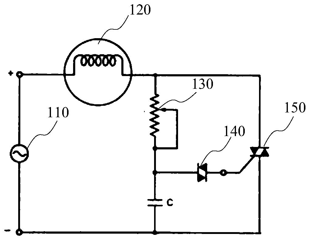
Figure 1 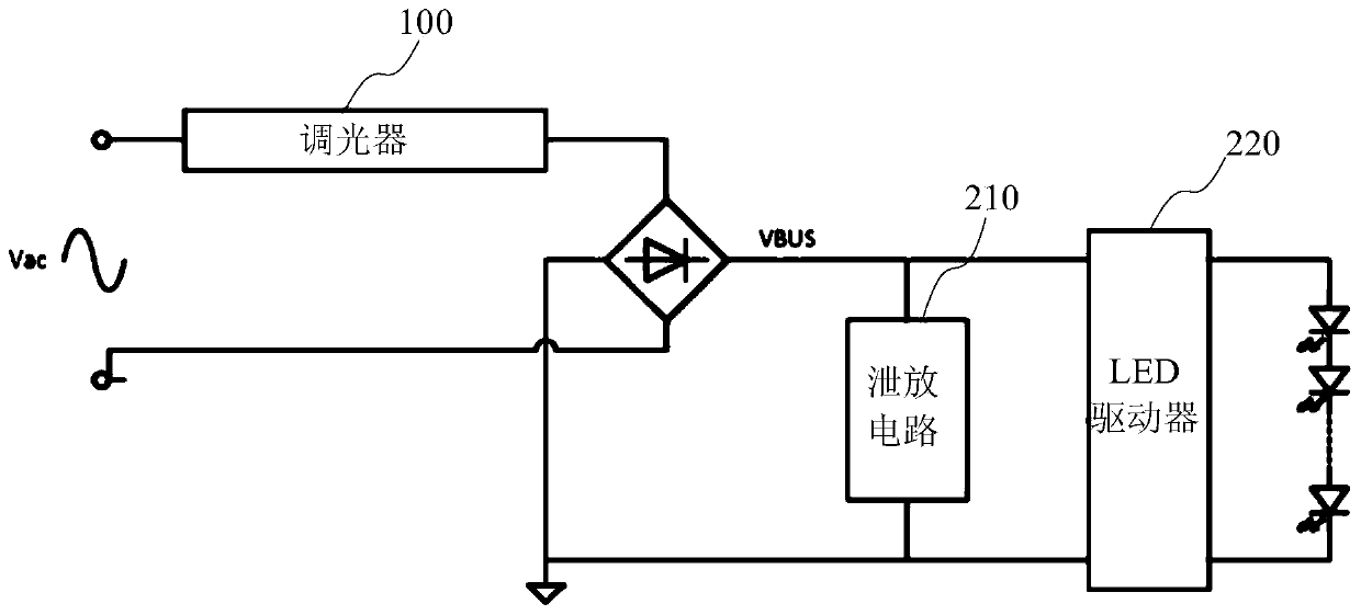
Figure 2 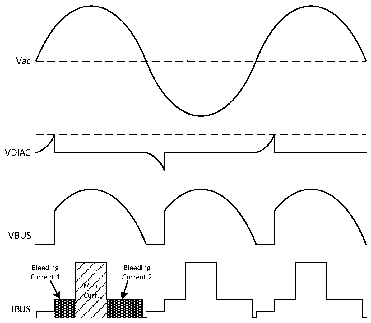
Figure 3
Abstract
Description
technical field
[0001] The invention relates to the technical field of lighting, in particular to a control circuit, a method, a chip, a driving system and a method of a discharge circuit. Background technique
[0002] LED (Light Emitting Diode), light-emitting diode, referred to as LED) lighting device has been widely used in the lighting industry and other fields used as indicator lights due to its advantages of low energy consumption, small size, and high durability. In one application of the LED lighting device, the brightness of the LED lamp is adjusted by a dimmer.
[0003] Typical thyristor dimmer circuit structure as figure 1 As shown, the potentiometer 130 and the capacitor C form a phase-shift trigger network. When the voltage across the capacitor C rises to the blocking voltage of the bidirectional trigger diode 140, the bidirectional trigger diode 140 breaks down, and the triac 150 is triggered to conduct. The power supply 110 supplies current to the light bulb...
Examples
Embodiment Construction
[0061] Embodiments of the present invention are described below through specific examples, and those skilled in the art can easily understand other advantages and effects of the present invention from the content disclosed in this specification. The present invention can also be implemented or applied through other different specific implementation modes, and various modifications or changes can be made to the details in this specification based on different viewpoints and applications without departing from the spirit of the present invention. It should be noted that, in the case of no conflict, the following embodiments and features in the embodiments can be combined with each other.
[0062] It should be noted that the structures, proportions, sizes, etc. shown in the drawings attached to this specification are only used to match the content disclosed in the specification, for those who are familiar with this technology to understand and read, and are not used to limit the s...