
Variable damping permanent magnet eddy current retarder
An eddy current damper, eddy current technology, applied in the direction of magnetic spring, spring/shock absorber, mechanical equipment, etc., can solve the problem of difficult to adjust damping synchronously, achieve high efficiency of magnetic energy utilization, easy processing and manufacturing, easy installation and disassembly Effect
Patent Information
- Authority / Receiving Office
- CN · China
- Patent Type
- Applications(China)
- Current Assignee / Owner
- Publication Date
- 2019-09-03
Smart Images
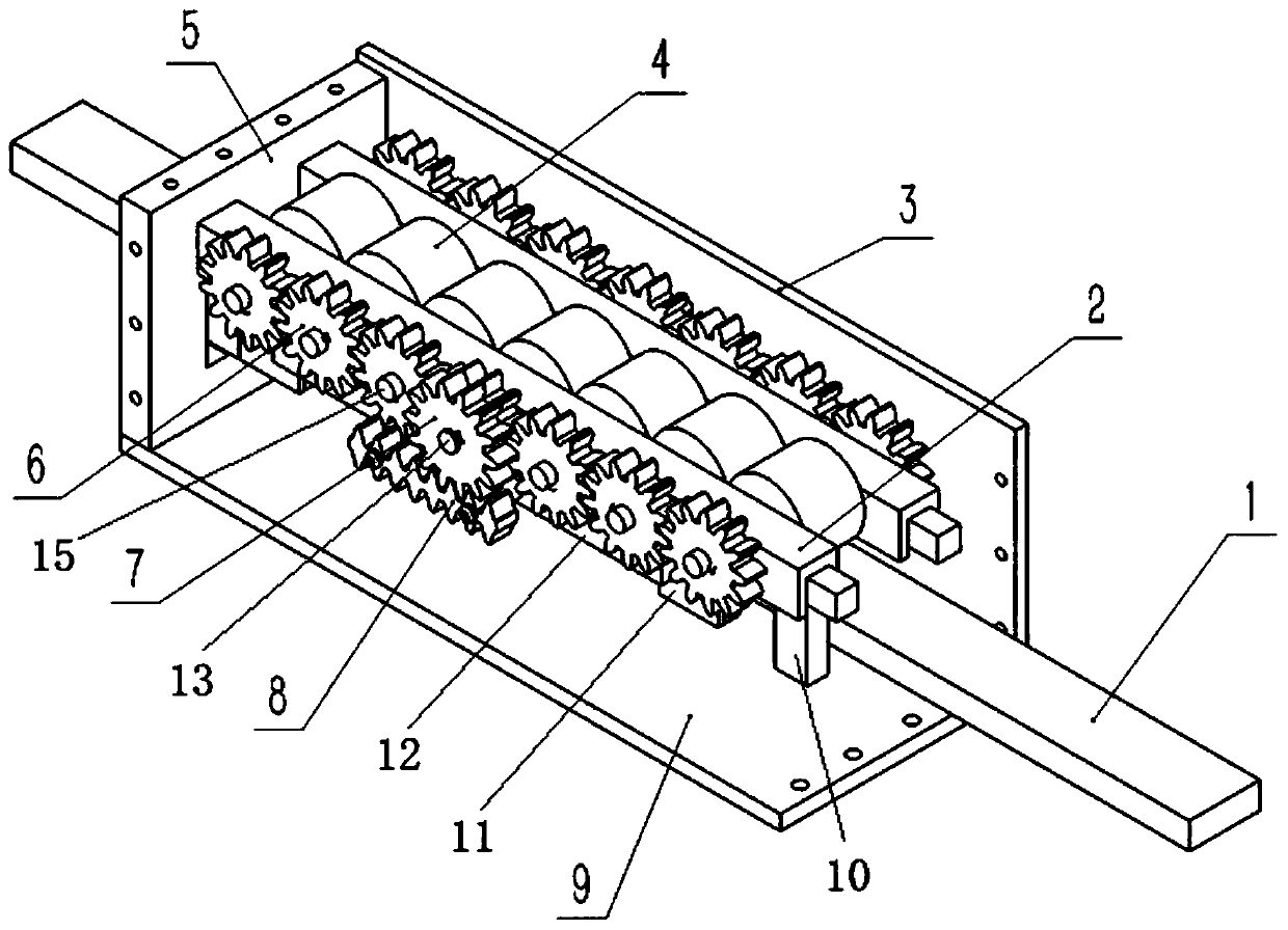
Figure 1 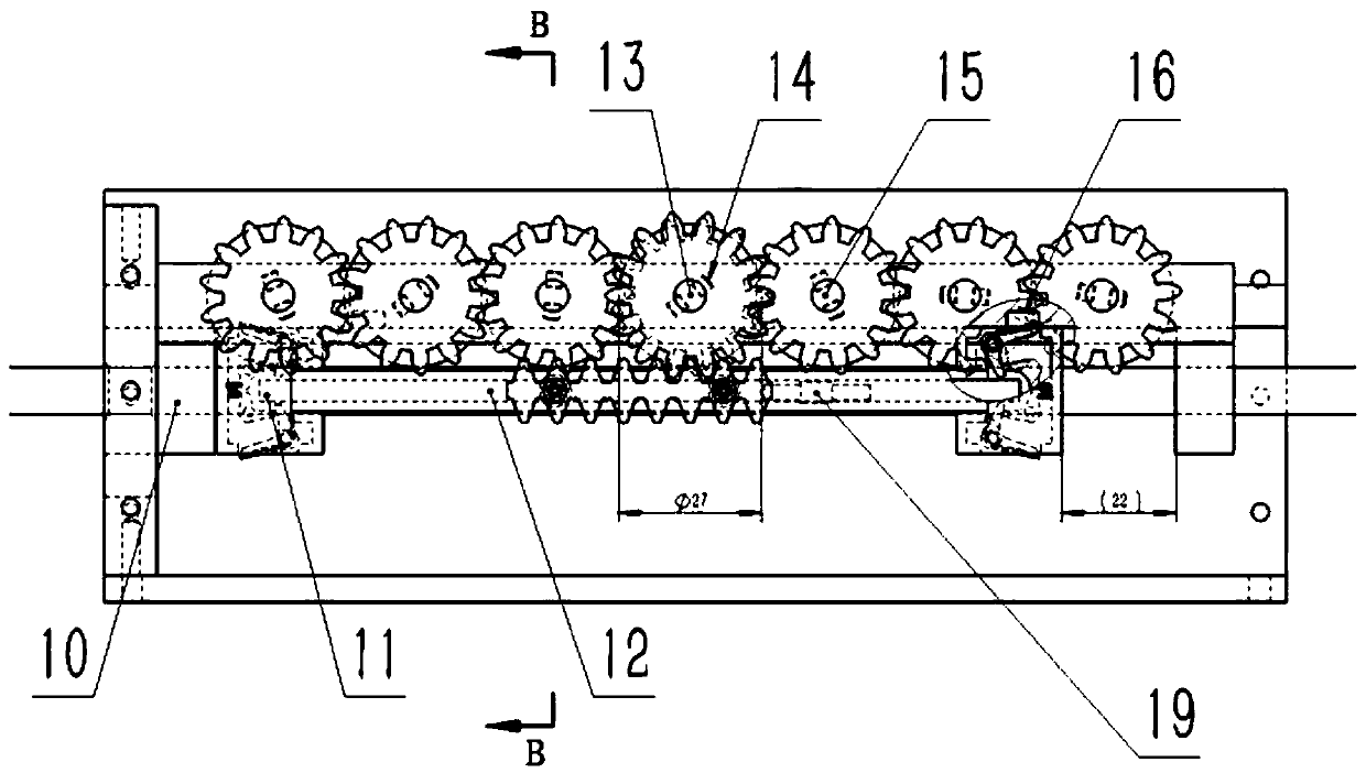
Figure 2 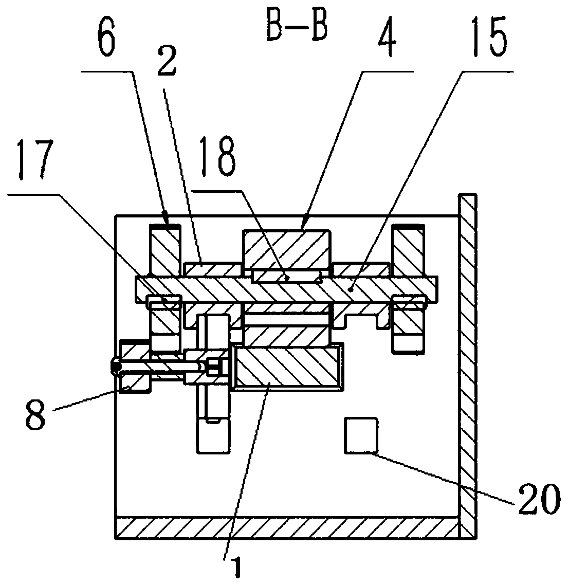
Figure 3
Abstract
Description
technical field
[0001] The invention belongs to the technical field of electromagnetic braking, and in particular relates to a variable damping permanent magnet electric eddy current damper. Background technique
[0002] According to the law of electromagnetic induction, when the conductor material and the magnetic field move relative to each other, an eddy current will be induced in the conductor, and the eddy current will excite an induced magnetic field. The role of the induced magnetic field is to hinder the relative movement between the conductor and the main magnetic field. A damping force (braking force). And the conductor material has resistance, and the eddy current will be dissipated in the form of heat energy. The eddy current damper is an inductive energy dissipation device based on the above principle.
[0003] Some buffer braking devices often require different damping for positive and negative strokes, and less damping is required for re-entry. The existing...
Examples
Embodiment Construction
[0042] Below in conjunction with appendix and specific embodiment, further illustrate the present invention, should be understood that these embodiments are only for illustrating the present invention and are not intended to limit the scope of the present invention, after having read the present invention, those skilled in the art will understand various aspects of the present invention Modifications in equivalent forms all fall within the scope defined by the appended claims of this application.
[0043] Such as Figure 1-8 As shown, a variable damping permanent magnet eddy current damper includes a displacement-eddy current generation assembly, a phase control assembly, a fixed support assembly, a positioning-lock assembly, and the fixed support assembly includes a support box and is arranged on a support The support limit block 10 in the box, the phase control assembly includes a support phase guide rail 2, a plurality of intermeshed driven gears 6 arranged on the support p...