
A split shaft device for bonding bamboo and wood straw processing
A technology of bamboo, wood and straws, which is applied in wood processing equipment, sugarcane machining, manufacturing tools, etc., and can solve the problems of reduced production efficiency, product scrapping, and high breakage rate of drill bits
Patent Information
- Authority / Receiving Office
- CN · China
- Patent Type
- Patents(China)
- Current Assignee / Owner
- Publication Date
- 2021-05-07
Smart Images
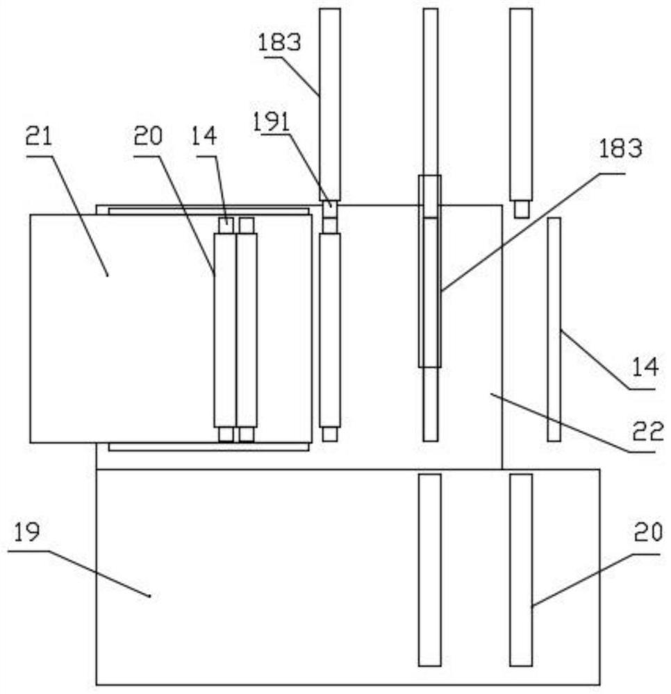
Figure 1 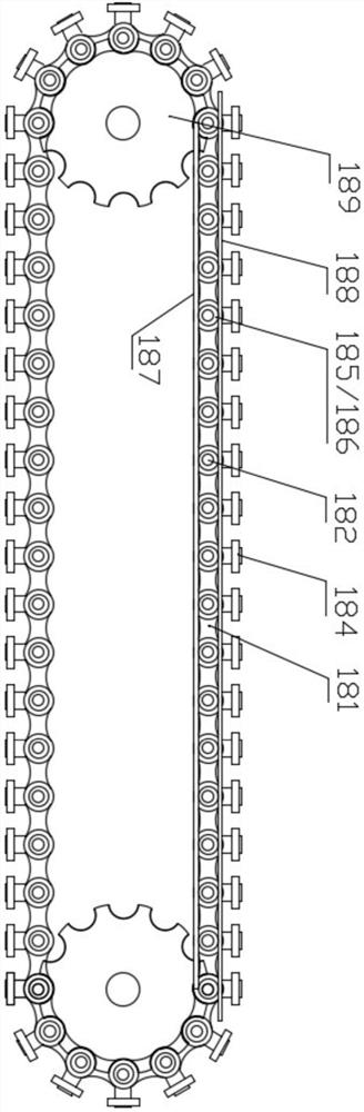
Figure 2 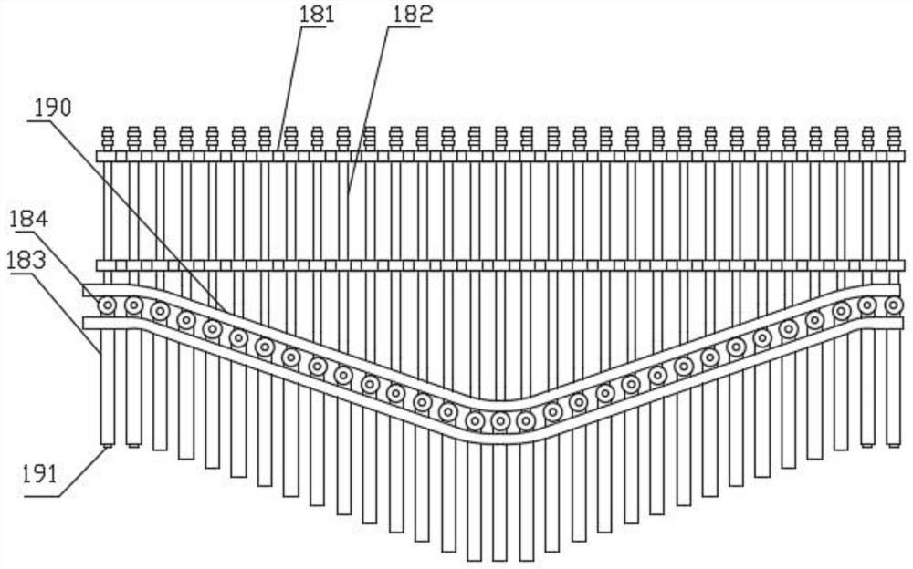
Figure 3
Abstract
Description
technical field
[0001] The invention belongs to the technical field of bamboo and wood straw processing, and in particular relates to a shaft-splitting device for bonding bamboo and wood straw processing. Background technique
[0002] Most of the straws used in the current food market are plastic straws, which have disadvantages such as poor high temperature resistance, poor degradation, non-environmental protection, and short service life, and related chemical substances need to be used in the manufacturing process. Ecological environmental protection and ecological cycle have a very large degree of harm. With the progress of social development, human beings are becoming more and more aware of the protection of the ecological environment. At present, most countries in the world have implemented or plan to implement the "plastic ban", and plastic straws will soon be eliminated from the market.
[0003] At present, bamboo tubes or wooden tubes have begun to appear in foreign...
Examples
Embodiment Construction
[0027] In order to enable those skilled in the art to better understand the technical solution of the present invention, the present invention will be described in detail below in conjunction with the accompanying drawings. The description in this part is only exemplary and explanatory, and should not have any limiting effect on the protection scope of the present invention. .
[0028] Such as Figure 1-6 As shown, a kind of split shaft device for bonding bamboo and wood straw processing, it is arranged on the discharge end of feeding conveyor belt 21, and it includes two synchronously moving chains 181; A central shaft 182 is arranged between them; the front end of the central shaft 182 extends from the end face of the chain 181 and is provided with an electromagnet 191, and the tail end extends from the end face of the chain 181 and is provided with a negative pole ring 186 and a positive pole ring 185; the positive pole The ring 185 is in contact with the positive rail 187...