
Band-type brake control method of servo motor
A technology of servo motor and control method, applied in the direction of electric motor/converter plug, etc., can solve the problems of large energy consumption and large current, and achieve the effect of reducing the power consumption of the brake, maintaining a small current, and preventing the system from running out of control.
Patent Information
- Authority / Receiving Office
- CN · China
- Patent Type
- Applications(China)
- Current Assignee / Owner
- Publication Date
- 2020-04-03
- Estimated Expiration
- Not applicable · inactive patent
Smart Images
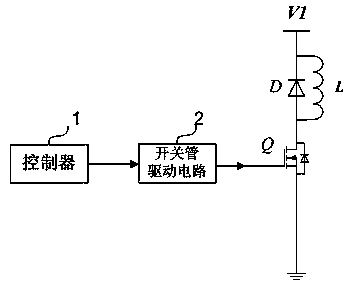
Figure 1 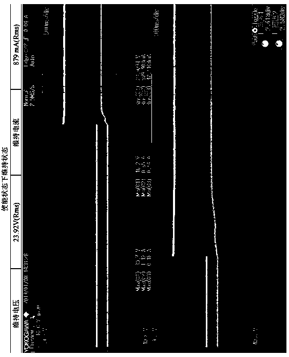
Figure 2 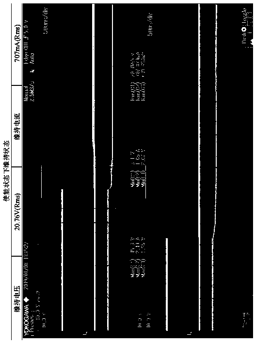
Figure 3
Abstract
Description
technical field
[0001] The invention relates to the control technology of a servo motor. Background technique
[0002] Servo motor driver is one of the core components of industrial robots. In the power supply mode of most servo motor drivers, the control power and the power power are separated. The control power needs to supply power to all the weak current circuits, and also needs to supply power to the brake of the servo motor. figure 1 The schematic diagram of the servo motor brake control circuit is shown. Such as figure 1 As shown, the servo motor brake control circuit includes a controller 1, a switch tube drive circuit 2, a switch tube Q, a brake electromagnetic coil L and a freewheeling diode D. The output terminal of the controller 1 is connected to the input terminal of the switch tube drive circuit 2, the output terminal of the switch tube drive circuit 2 is connected to the control terminal of the switch tube Q, and the first conduction terminal of the switch...
Examples
Embodiment Construction
[0014] The present invention will be further described below in conjunction with the accompanying drawings.
[0015] Please refer to figure 1 . A brake control method for a servo motor according to an embodiment of the present invention includes the following steps:
[0016] The controller 1 controls the switching tube Q to be turned on, so that the brake electromagnetic coil L is energized to work, wherein the switching tube Q is set on the path where the brake opening voltage V1 supplies power to the brake electromagnetic coil L;
[0017] The controller 1 outputs a PWM signal to the switch tube Q after the preset time t1 has elapsed from the time when the switch tube Q is turned on, and adjusts the duty cycle of the PWM signal output to the switch tube Q, so that the brake electromagnetic coil L The operating voltage gradually decreases until it reaches a preset maintenance voltage, and the preset maintenance voltage is lower than the opening voltage of the brake.
[0018...