
A surgical instrument control method for a laparoscopic surgical robot
A surgical robot and surgical instrument technology, applied in the field of robotics, can solve problems affecting surgical quality, poor flexibility, operator fatigue, etc., and achieve the effect of improving surgical quality, reducing life-threatening, and improving surgical efficiency
Patent Information
- Authority / Receiving Office
- CN · China
- Patent Type
- Patents(China)
- Current Assignee / Owner
- Publication Date
- 2021-06-18
Smart Images
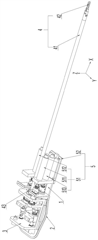
Figure 1 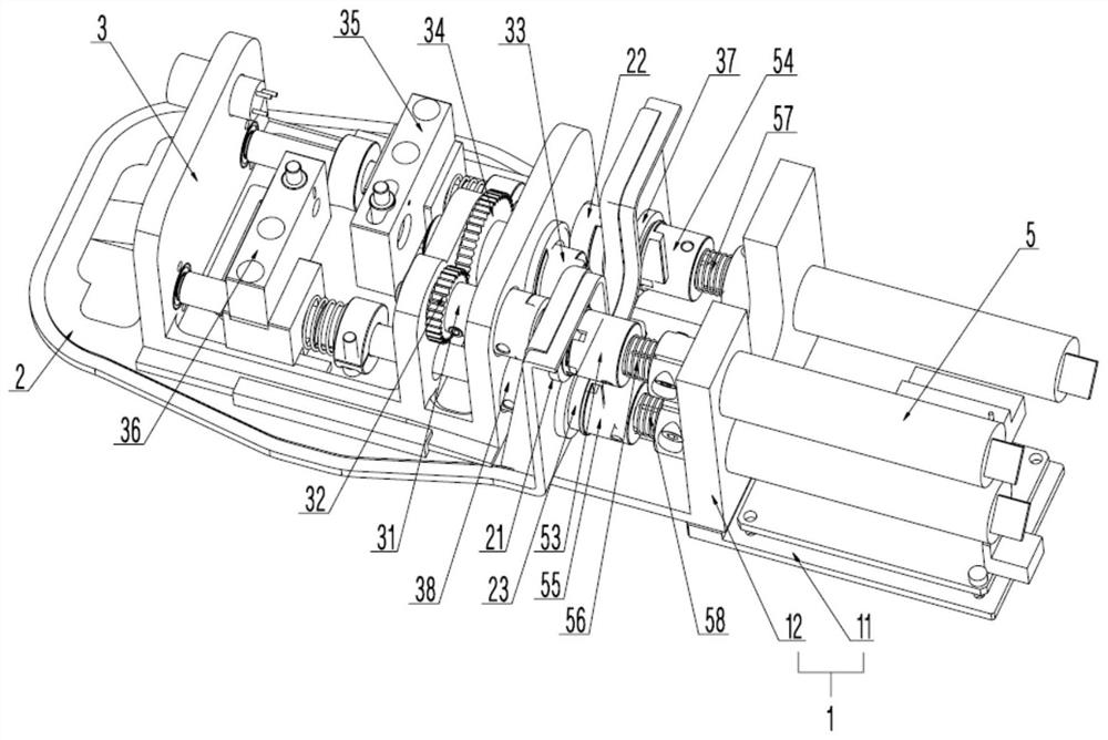
Figure 2 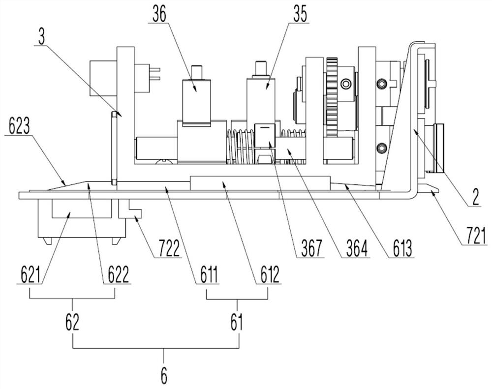
Figure 3
Abstract
Description
technical field
[0001] The invention relates to the technical field of robots, in particular to a method for controlling surgical instruments of a laparoscopic surgical robot. Background technique
[0002] In minimally invasive surgery, medical personnel are often required to manually cut, strip, suture and other operations on tissues. Especially for complex surgical operations, medical staff often need to operate surgical instruments for a long time to perform operations. This is a challenge to the doctor's physical strength and energy, which in turn affects the quality of the operation.
[0003] The existing minimally invasive surgical instruments are often simple imitations of traditional open surgical instruments, with less freedom, poor flexibility, and often high friction inside the instrument, which leads to attenuation of transmission force and fatigue of the operator, especially It is the hand tremors caused by the operator's fatigue that will reduce the accuracy ...
Examples
Embodiment 1
[0127] In a first embodiment of the invention, a surgical instrument 42 has a first degree of freedom (eg, an endoscope). Here, the first degree of freedom of the surgical instrument 42 means that the surgical instrument 42 can rotate around the axis of the instrument shaft 41 of the instrument connection mechanism 4 as the rotation axis (ie, along the X-axis direction). The first degree of freedom of the surgical instrument 42 can mimic the rotational motion of a human arm.
[0128] In this embodiment, the power source 51 of the driving mechanism 5 includes a first motor 511 , and the output shaft of the first motor 511 is disposed in the first hole 121 on the side wall of the fixing seat 12 of the driving seat 1 . In order to improve space utilization, the axial direction of the instrument shaft 41 , the axial direction of the first motor 511 and the length direction of the fixing seat 12 are the same.
[0129] Specifically, the power transmission mode of the first motor 51...
Embodiment 2
[0152] In the second embodiment of the present invention, the surgical instrument 42 has a second degree of freedom (such as a scalpel that cuts only at designated locations). Here, the second degree of freedom of the surgical instrument 42 means that the surgical instrument 42 can be deflected around the Z-axis. The second degree of freedom of the surgical instrument 42 can imitate the deflection action of the human wrist joint.
[0153] In this embodiment, the power source 51 includes a second motor 512 , and the output shaft of the second motor 512 is disposed in the second hole 122 on the side wall of the fixing seat 12 . In order to improve space utilization, the axial direction of the instrument shaft 41 , the axial direction of the second motor 512 and the length direction of the fixing seat 12 are the same.
[0154] In this embodiment, the power output by the second motor 512 is transmitted to the instrument rod 41 through the first lead screw 354 and the first seat 3...
Embodiment 3
[0183] In the third embodiment of the present invention, the surgical instrument 42 has a third degree of freedom (for example, surgical scissors that only cut at specified positions). Here, the third degree of freedom of the surgical instrument 42 means that the surgical instrument 42 can be opened and closed. The third degree of freedom of the surgical instrument 42 can imitate the closing and opening movements of human fingers.
[0184] In this embodiment, the power source 51 includes a third motor 513 , and the output shaft of the third motor 513 is disposed in the third hole 123 on the side wall of the fixing seat 12 . In order to improve space utilization, the axial direction of the instrument shaft 41 , the axial direction of the third motor 513 and the length direction of the fixing seat 12 are the same.
[0185] In this embodiment, the power output by the third motor 513 is transmitted to the instrument rod 41 through the second lead screw 364 and the second seat 36 ...