
Magnetofluid shock absorber for cutter head
A magnetic fluid and shock absorber technology, applied in the direction of shock absorber, shock absorber-spring combination, shock absorber, etc., can solve the problems that cannot be used to control the vibration of the cutter head, and the vibration frequency range is narrow, so as to achieve real-time Regulatory control, fast response, and improved control efficiency
Patent Information
- Authority / Receiving Office
- CN · China
- Current Assignee / Owner
- Publication Date
- 2020-05-19
- Estimated Expiration
- Not applicable · inactive patent
Smart Images
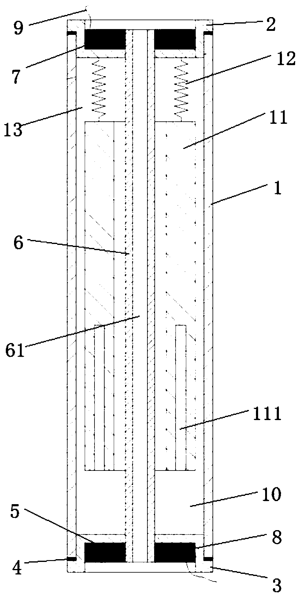
Figure 1 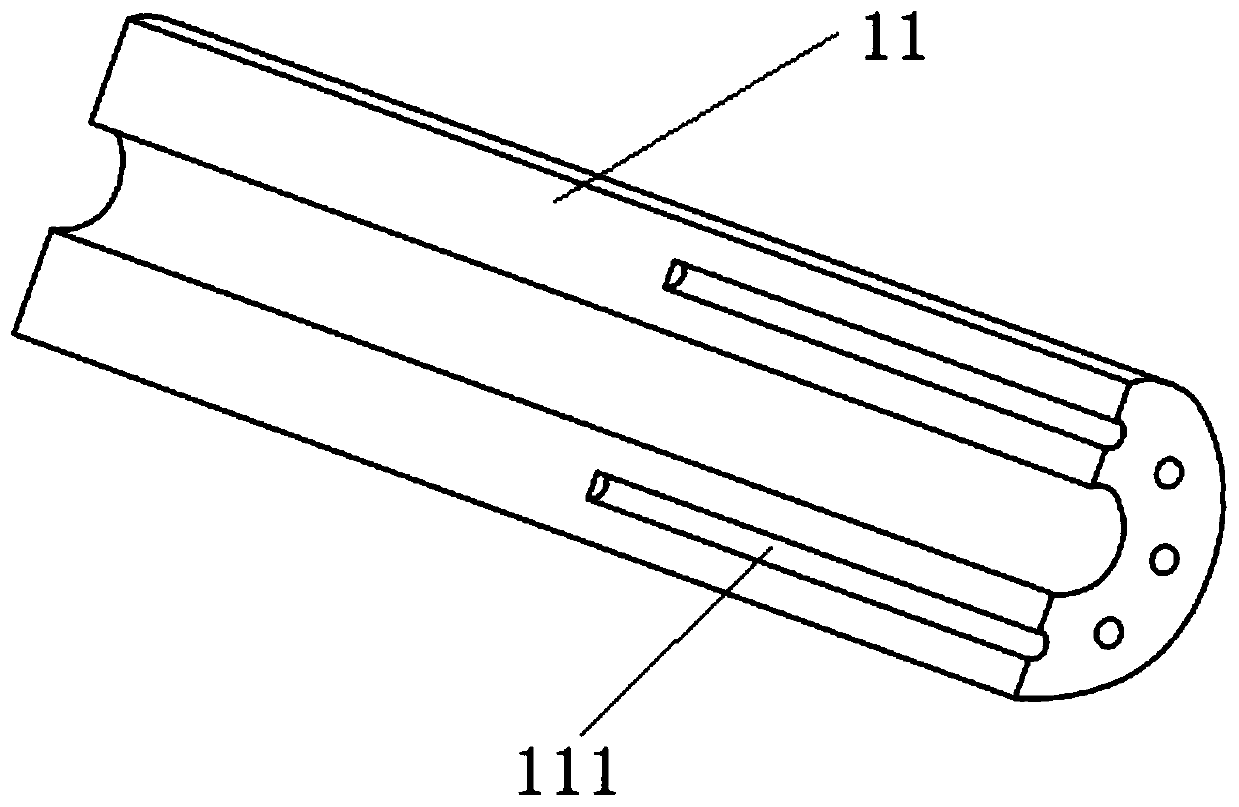
Figure 2 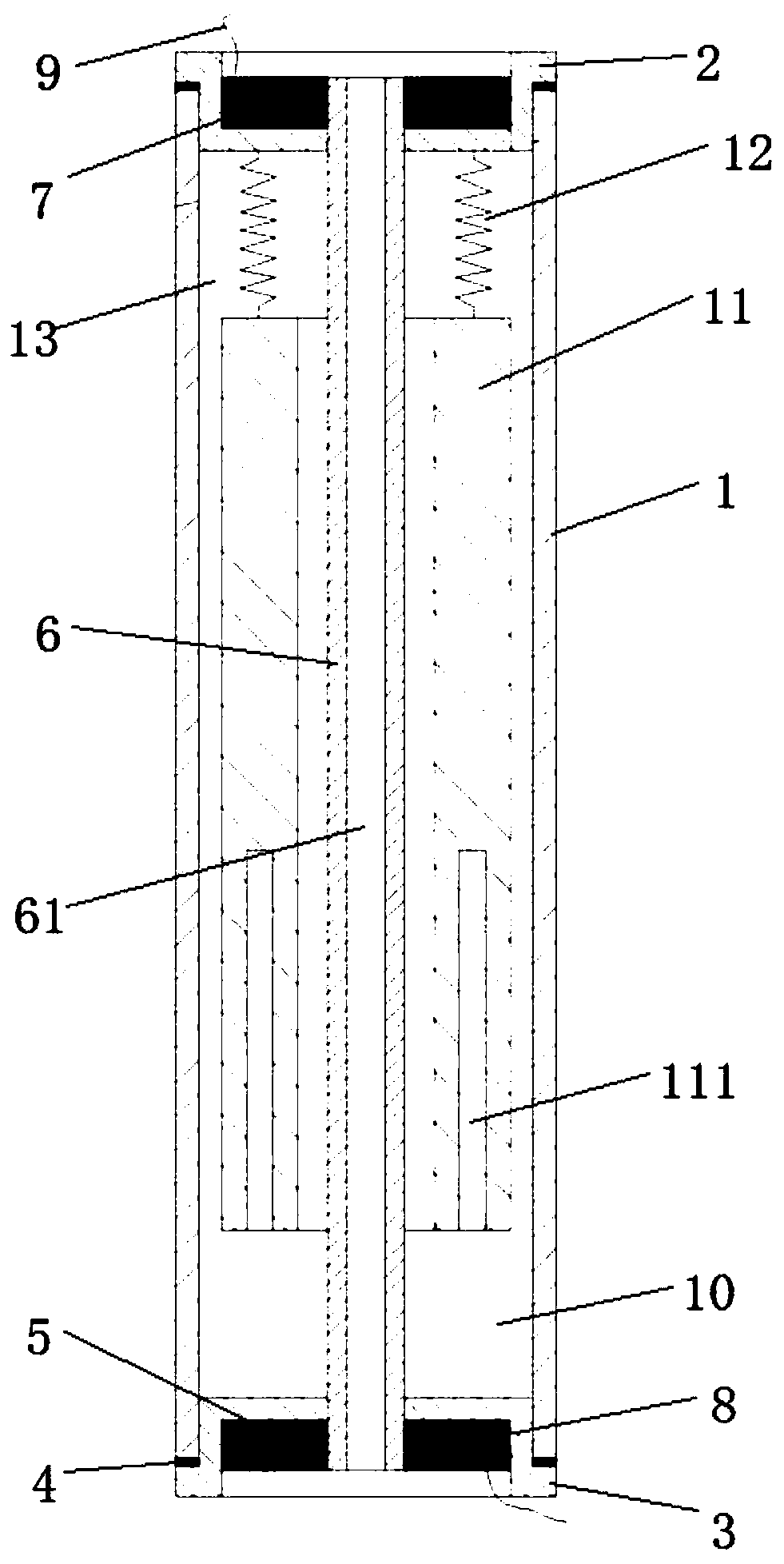
Figure 3
Abstract
Description
technical field
[0001] The invention relates to the technical field of shock absorbers, in particular to a magnetic fluid shock absorber for a cutter head. Background technique
[0002] When the turning and milling machine is working, the cutter head will vibrate violently or vibrate, which is an important reason for the low machining accuracy of the product. Nowadays, the shock absorbers used to control the vibration of machine tool heads are mostly passive shock absorbers, such as rubber metal rubber shock absorbers, tuned mass damping shock absorbers, rubber vibration isolators, etc.
[0003] However, the vibration of the cutter head is complicated, the vibration frequency band is wide, the control frequency range of the passive damper or tuned mass damper is narrow, and the adjustment of the traditional damper used to control the vibration of the cutter head is cumbersome and has great limitations.
[0004] The damping of the magnetic fluid can be changed according to t...
Examples
Embodiment Construction
[0019] The present invention will be further described below in conjunction with accompanying drawing and embodiment:
[0020] Such as figure 1 with figure 2 As shown, a magnetic fluid shock absorber for a cutter head of the present invention includes a housing 1 with a hollow structure. The outer profile of the housing 1 is circular, and the hollow structure inside it is cylindrical. An upper end cover 2 and a lower end cover 3 are fixedly installed, and a sealing ring 4 is arranged between the upper end cover 2 and the housing 1 and between the lower end cover 3 and the housing 1, and the sealing ring 4 can prevent the leakage of the magnetic fluid 13; the upper end cover 2 and the lower end cover 3 are provided with a groove 5, the center of the housing 1 is provided with a cooling pipe 6 that is vertically arranged and fixedly connected with the upper end cover 2 and the lower end cover 3, and the center of the cooling pipe 6 is provided with a through hole 61, Cooling ...