
A self-rotating quantitative filling machine for mushroom liquid
A self-rotating, filling machine technology, applied in mushroom cultivation, agricultural gas emission reduction, gardening, etc., can solve the problems of low filling efficiency and frequent operation, and achieve the effect of simple and convenient use
Patent Information
- Authority / Receiving Office
- CN · China
- Patent Type
- Patents(China)
- Current Assignee / Owner
- Publication Date
- 2022-08-09
Smart Images
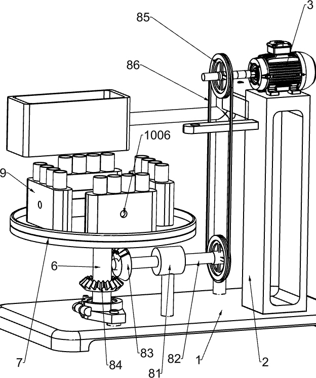
Figure 1 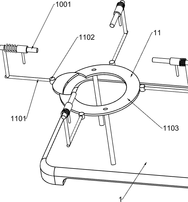
Figure 2 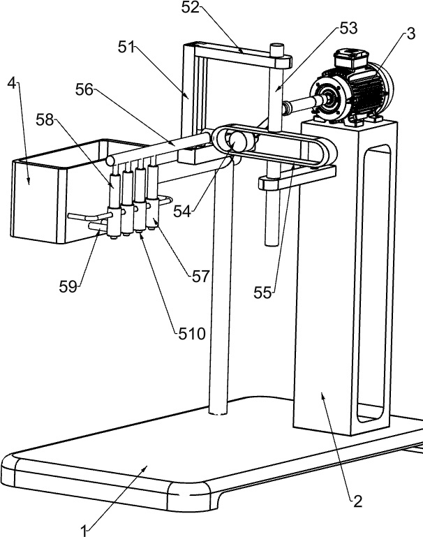
Figure 3
Abstract
Description
technical field
[0001] The invention relates to a filling machine, in particular to a mushroom liquid self-rotating quantitative filling machine. Background technique
[0002] Liquid culture technology is a relatively advanced plant cultivation method. This cultivation method is favored by many plant growers because of its ability to multiply plants. At present, most mushroom cultivation adopts liquid cultivation. It is injected into the test tube, and then the mushrooms are cultivated in the test tube. However, the manual operation is used to inject the mushroom liquid into the test tube. The worker takes the test tube again and again, injects the mushroom liquid, and then replaces the next test tube. This manual operation method requires workers Continuous operation requires repeated removal and replacement of test tubes, resulting in low filling efficiency.
[0003] In view of the above-mentioned manual filling method of mushroom liquid, there are too many workers' opera...
Examples
Embodiment 1
[0037] A mushroom liquid self-rotating quantitative filling machine, such as figure 1 shown, including a support 1, a support table 2, a gear motor 3, a solution tank 4, a liquid adding mechanism 5, a material replacement shaft 6, a disc 7, a replacement mechanism 8 and a test tube placement box 9. The right side of the support 1 is provided with Support table 2, a geared motor 3 is installed on the top of the support table 2, a solution tank 4 is arranged on the rear side of the support 1, and a liquid addition mechanism 5 is installed between the front of the solution tank 4 and the left side of the support table 2, and the liquid addition mechanism 5 is connected to the support table 2. The geared motor 3 is connected, the material replacement shaft 6 is rotatably installed on the left side of the support 1, the top of the material replacement shaft 6 is connected with a disc 7, the left side of the support 1 and the lower part of the material replacement shaft 6 are provide...
Embodiment 2
[0040] special reference Figure 1-3 As shown, the liquid adding mechanism 5 includes a vertical slide rail 51, a support rod 52, a slide rod 53, a drive shaft 54, a lateral slide rail 55, a lift rod 56, a feeding cylinder 57, a piston 58, a liquid inlet pipe 59 and a liquid outlet Tube 510, a vertical slide rail 51 is provided on the upper rear side of the support table 2, a support rod 52 is installed on the front side of the upper part of the vertical slide rail 51 and the upper side of the left part of the support table 2, and the upper support rod 52 supports the front side and the bottom A sliding rod 53 is slidably arranged between the left side of the rod 52, a transverse sliding rail 55 is installed in the middle of the sliding rod 53, a driving shaft 54 is provided on the output shaft of the deceleration motor 3, and the left side of the driving shaft 54 is located in the transverse sliding rail 55, A lift rod 56 is slidably installed in the vertical slide rail 5...
Embodiment 3
[0045] Specifically, as Figure 4-5 As shown, a fixing mechanism 10 is also included. The fixing mechanism 10 includes a cross rod 1001, a placing sleeve 1002, a fixed sleeve 1003, a moving insertion rod 1004 and a spring 1005. The cross rod 1001 is installed on the top of the disc 7, and the ends of the cross rod 1001 are provided with There is a placing sleeve 1002, the test tube placing box 9 is located in the placing sleeve 1002, the disc 7 is evenly provided with four fixing sleeves 1003, the fixing sleeves 1003 are located outside the placing sleeve 1002, and a movable inserting rod 1004 is slidably arranged in the fixing sleeve 1003, A spring 1005 is connected between the side of the fixed sleeve 1003 and the outer side of the movable plunger 1004 , the placing sleeve 1002 and the outer middle of the test tube placing box 9 have a circular hole 1006 , and the inner side of the movable plunger 1004 is located in the circular hole 1006 .
[0046] When the mushroom liquid ...