
Real-time adjusting device and method for girder line type in bridge pushing process
A real-time adjustment and jacking technology, used in bridges, bridge construction, erection/assembly of bridges, etc., can solve problems such as ensuring the smooth upper pier and excessive lower deflection of the main girder, reducing construction safety risks and applying span Increased, easy design and construction effects
Patent Information
- Authority / Receiving Office
- CN · China
- Current Assignee / Owner
- Publication Date
- 2020-08-25
Smart Images
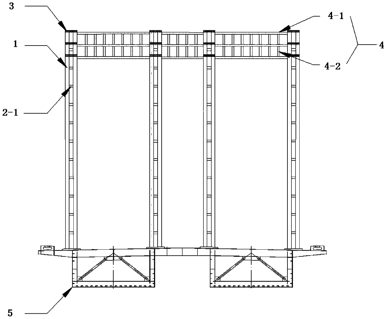
Figure 1 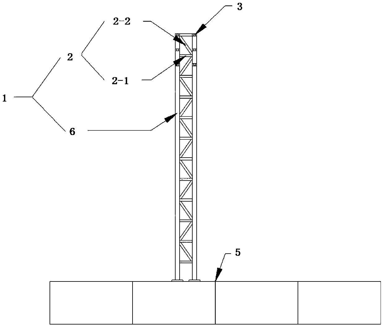
Figure 2 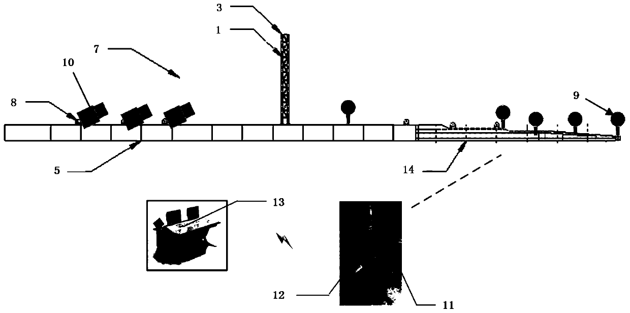
Figure 3
Abstract
Description
technical field
[0001] The invention relates to the technical field of bridge construction, in particular to a real-time adjustment device and an adjustment method for the line shape of a main girder during the bridge pushing process. Background technique
[0002] The jacking construction method is a common construction method for urban bridges. It has the advantages of fast and simple construction and less impact on traffic. It is especially suitable for the construction of long-span and long-lead cross-section beam bridge projects in cities. With the development of bridge engineering in our country, the span and weight of newly-built bridge structures continue to increase. In the process of main girder jacking, if the traditional jacking construction method is adopted, the deflection of the beam end of the cantilever section of the main girder is too large. There is no way to guarantee that the main beam will go up the pier smoothly. In order to solve this problem, it is ...
Examples
Embodiment Construction
[0039] see Figure 1 to Figure 3 , in a preferred embodiment of the present invention, a device for real-time adjustment of the main girder alignment during the bridge pushing process, including a cable tower 1, a cross-connection between the cable towers 4, a stay cable 7, and a beam body anchoring device 8 , Intelligent tensioning jack 10, automatic linear measurement system, intelligent adjustment system 13.
[0040]The cable tower 1 includes at least two steel pipe columns 6, web members 2 and cable saddles 3, at least two steel pipe risers are arranged at intervals along the width direction of the steel box girder section 5, and the bottom thereof is consolidated with the steel box girder web , in this embodiment, four steel pipe columns 6 are provided, and the height of each steel pipe column 6 is the same, which is 1 / 2.7 to 1 / 3.7 of the maximum span of the bridge. Specifically, the steel pipe column 6 is Φ630mm × 12mm steel pipe. Each steel pipe column 6 is provided w...