
A finite element method for structural analysis of composite beam with initial defects
A technology of structural analysis and finite element, applied in special data processing applications, instruments, geometric CAD, etc., to achieve the effect of improving calculation accuracy, high calculation efficiency, and eliminating concentration
Patent Information
- Authority / Receiving Office
- CN · China
- Current Assignee / Owner
- Publication Date
- 2020-10-16
Smart Images
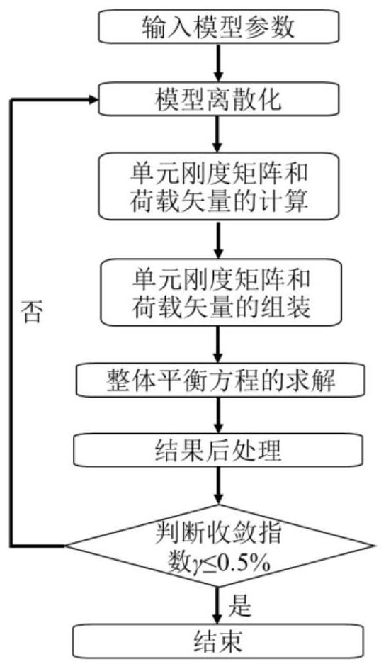
Figure 1 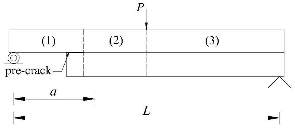
Figure 2 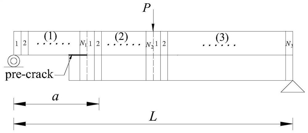
Figure 3
Abstract
Description
technical field
[0001] The invention relates to a method in the technical field of mechanical numerical simulation, in particular to a finite element method for structural analysis of composite beams with initial defects. Background technique
[0002] The finite element method (Finite element method, referred to as FEM) is a mature numerical calculation method, which has been widely used in various engineering fields and has been widely adopted by various engineers. Its advantage is that each parameter has a clear physical meaning, and it can solve structures with various complex boundary conditions and geometric configurations. The combined structure can give full play to the mechanical properties of the component materials, and has been widely used in aerospace, civil engineering, mechanical engineering and other fields. However, due to sudden changes in material properties, the combined structure is prone to debonding at the interface, which affects its mechanical proper...
Examples
Embodiment 1
[0075] Such as figure 1 As shown, this embodiment includes the following steps:
[0076] (a) Input model parameters.
[0077] This embodiment is a static loading simulation of a single leg bending (SLB for short) specimen, such as figure 2 As shown, the length L of the sample is 0.1m, the initial length of the crack is 0.025m, the height of the upper sub-beam ① and the lower sub-beam ② are both 0.002m, and the width is 0.001m. The material parameters of the upper and lower sub-beams are shown in Table 1, and the concentrated load P is 8N.
[0078] Table 1 Material parameters of samples
[0079]
[0080] (b) Discretization of the model.
[0081] First will be as figure 2 The shown embodiment SLB sample is divided into 3 areas, i.e. the cracked area (1), the uncracked area (2) on the left side of the loading point (concentrated load P action point) and the uncracked area (3) on the right side of the loading point; Set a certain number of cells per locale, such as ima...