
Electronic product environment test system with sample protection function
A protection function and technology for electronic products, applied in the field of electronic product environmental test systems, can solve problems such as sample short circuit, current rise, damaged samples, etc., and achieve the effects of improving test efficiency, convenient setting, and avoiding damage
Patent Information
- Authority / Receiving Office
- CN · China
- Patent Type
- Applications(China)
- Current Assignee / Owner
- Publication Date
- 2020-12-01
- Estimated Expiration
- Not applicable · inactive patent
Smart Images

Figure 1 
Figure 2 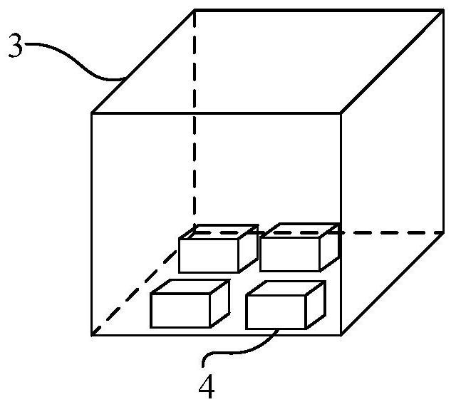
Figure 3
Abstract
Description
technical field
[0001] The invention relates to a test device, in particular to an electronic product environment test system with a sample protection function. Background technique
[0002] Environmental testing is to simulate different actual environments, simulate the damage caused by electronic components, automotive electronic products and other modern industrial products, and let the tested samples be tested in the simulated environment, such as pressure, temperature, humidity, aging and other tests. When conducting environmental tests, it is sometimes necessary to conduct an electrical test on the sample. In the case of power-on test, if the voltage or current value of the external power supply increases, or the current required by the sample appears in a certain experimental environment, it may cause a short circuit of the sample and damage the sample, which greatly increases the test time. cost. Contents of the invention
[0003] The object of the present invent...
Examples
Embodiment 1
[0023] In the existing environmental test, it is required that the sample should not be short-circuited due to the increase of the voltage or current value of the external power supply, or the increase of the current required by the sample in a certain experimental environment, and the protection from the outside world should be carried out. The samples are disconnected in time to ensure that the samples do not appear damaged. Such as figure 1 As shown, the present embodiment provides an electronic product environmental testing system with a sample protection function, including a DC power supply 1, a sample protection device 2 and an environmental test chamber 3, and the sample protection device 2 is respectively connected to the DC power supply 1 and installed in the environmental test chamber Sample 4 in 3, sample protection device 2 includes a DC power input terminal, a voltage and current limiting unit, and a power output terminal connected in sequence, the DC power input...
Embodiment 2
[0027] In the electronic product environmental test system with sample protection function provided by this embodiment, such as figure 2 As shown, the voltage limiting and current limiting unit also includes a first reactor L 1 , the second reactor L 2 , the first capacitance C 1 , the second capacitance C 2 and Zener diode D, the first reactor L 1 One end is connected to the fuse FU, the other end is connected to one terminal of the power output terminal, the fuse FU is connected to one terminal of the DC power input terminal, and the second reactor L 2 One end is connected to the other terminal of the DC power input terminal, the other end is connected to the other terminal of the power output terminal, and the first capacitor C 1 , Zener diode D and the second capacitor C 2 Connect them in parallel with the output terminals of the power supply in turn.
[0028] In this embodiment, the first reactor L 1 and the second reactor L 2 Both are magnetic core reactors or i...