
A conductive foam positioning die-cutting device
A technology of conductive foam and positioning mold, which is applied in cleaning methods and appliances, chemical instruments and methods, and cleaning methods using gas flow, etc., which can solve the problems of affecting the flatness of the incision, sticking dust, and unevenness of the cut. Achieve the effects of reducing dust adhesion, improving work efficiency and maintaining flatness
Patent Information
- Authority / Receiving Office
- CN · China
- Patent Type
- Patents(China)
- Current Assignee / Owner
- Publication Date
- 2022-04-01
Smart Images
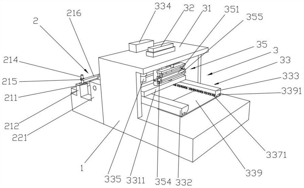
Figure 1 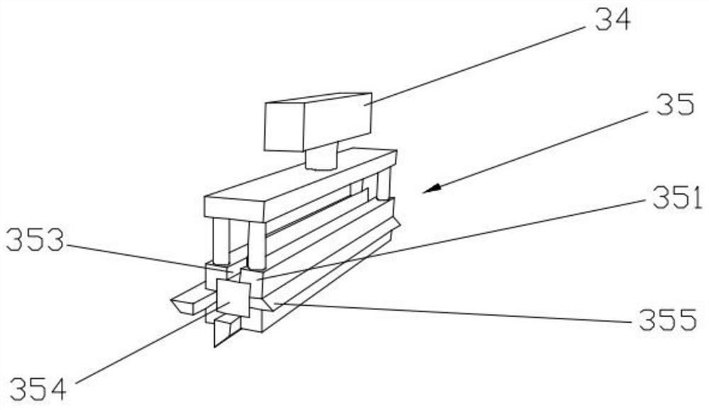
Figure 2 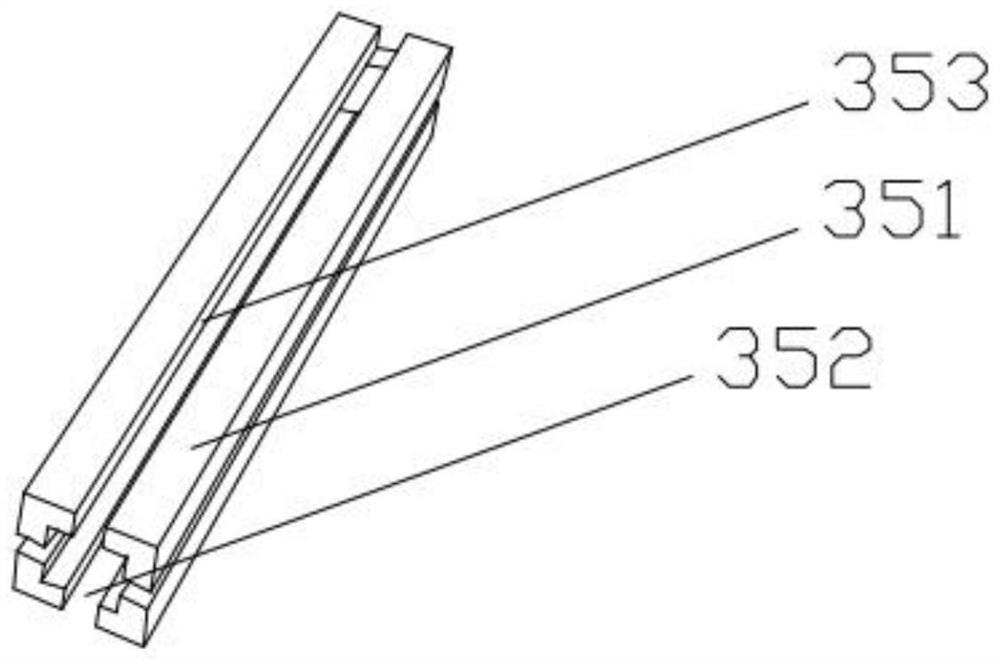
Figure 3
Abstract
Description
technical field
[0001] The invention relates to the technical field of conductive foam processing equipment, in particular to a positioning die-cutting device for conductive foam. Background technique
[0002] Conductive foam, that is, wrapping conductive cloth on the flame-retardant sponge, after a series of treatments, it has good surface conductivity, and can be easily fixed on the device to be shielded with adhesive tape. When encountering radio waves, it will According to the nature of the object, it can reflect, absorb, and provide excellent shielding effect. It is widely used in PDP TV, LCD monitor, LCD TV, mobile phone, notebook computer, MP3, communication cabinet, medical equipment and other electronic products as well as military and aerospace fields. .
[0003] Conductive foam is cut according to the required length before use and then spliced later. At present, in the production process, the operator usually uses scissors or a cutter to cut the conductive foa...
Examples
Embodiment Construction
[0027] Specific embodiments of the present invention will be described below in conjunction with the accompanying drawings.
[0028] Such as Figure 1-7 As shown, it is a conductive foam positioning die-cutting device of this embodiment, which includes a die-cutting frame 1, and a feeding leveling device 2 and a cutting device 3 are arranged side by side on the top surface of the die-cutting frame 1. The feeding leveling device 2 includes a limit feed rod device 21 and a feed roller device 22, the limit feed rod device 21 and the feed roller device 22 are arranged side by side on the top surface of the die-cutting frame 1 in sequence, and the limit feed rod device 21 includes a limit Rod body 211, the two ends of limit rod body 211 are all provided with limit bar seat 212, and limit bar seat 212 is fixedly arranged on the top surface of die-cutting frame 1, and the side wall of limit bar seat 212 is all provided with limit bar Adjustment groove 213, both ends of the limit rod...