
A vertical automatic casting cutting machine
A technology for cutting machines and castings, applied in the direction of maintenance and safety accessories, metal processing machinery parts, metal processing equipment, etc., can solve the problems of ground pollution, metal powder scattering, etc., and achieve the effect of convenient collection box, convenient movement and convenient sealing
Patent Information
- Authority / Receiving Office
- CN · China
- Patent Type
- Patents(China)
- Current Assignee / Owner
- Publication Date
- 2022-07-29
Smart Images
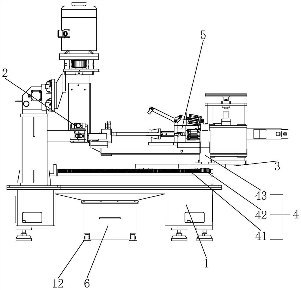
Figure 1 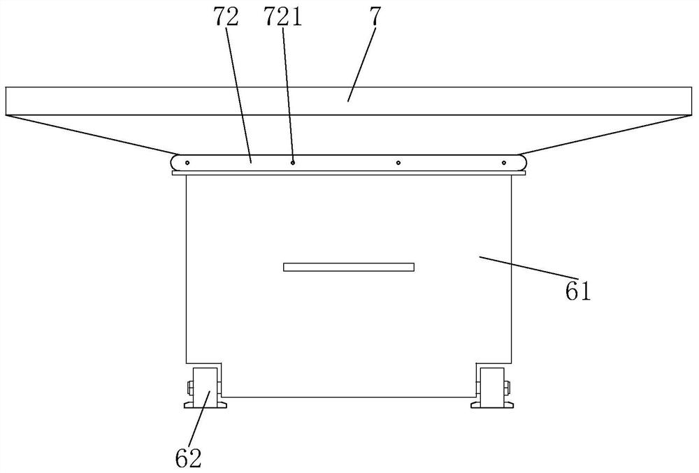
Figure 2 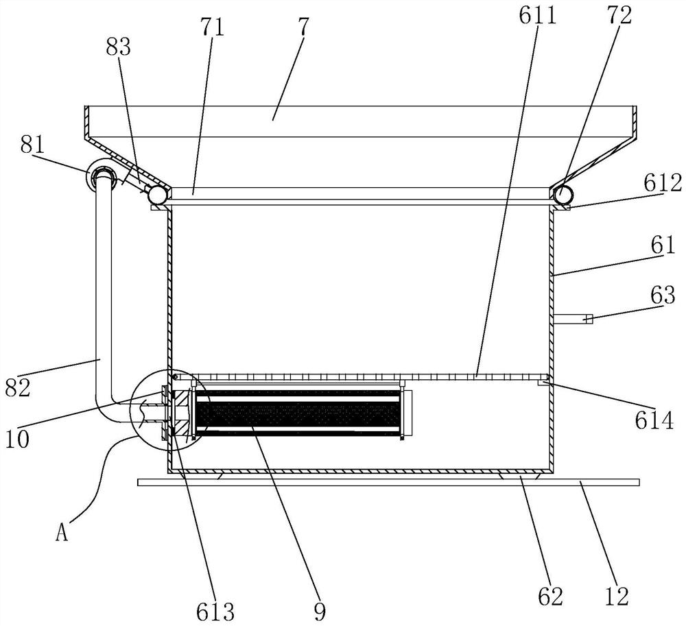
Figure 3
Abstract
Description
technical field
[0001] The invention relates to the technical field of cutting equipment, in particular to a vertical automatic casting cutting machine. Background technique
[0002] When manufacturing the metal parts of the water jet loom, the parts are made through the steps of casting, shell making, cutting, post-processing, etc. The products after casting include a mold shell and a plurality of castings integrally formed on the mold shell. In the cutting step, the function is to cut a plurality of castings located on the mold shell.
[0003] At present, the Chinese patent with the authorization announcement number of CN211840436U and the authorization announcement date of November 3, 2020 discloses an automatic casting cutting machine, which includes a machine tool, a cutting device arranged at one end of the machine tool, and a sliding table slidably arranged at the other end of the machine tool , a first drive mechanism arranged between the machine tool and the slidin...
Examples
Embodiment
[0026] Example: a vertical automatic casting cutting machine, such as figure 1 As shown, it includes a machine tool 1, a cutting device 2 arranged at one end of the machine tool 1, a sliding table 3 slidably arranged at the other end of the machine tool 1, a driving mechanism 4 arranged between the machine tool 1 and the sliding table 3 and driving the sliding table 3 to move, The mold shell side bump holding device 5 is arranged on the sliding table 3 and is used for holding the mold shell, and the collecting device 6 is used for collecting the castings dropped after cutting. The driving mechanism 4 includes a rack 41 provided on the machine tool 1 and extending along the sliding direction of the slide table 3, a second reduction motor 42 provided on the slide table 3, and an output shaft of the second reduction motor 42 provided on the output shaft. The gear 43 with which the rack 41 meshes.
[0027] like Figure 1 to Figure 3 As shown, the machine tool 1 is fixedly provid...