
Capacitance sensing equipment and laser cutting head
A capacitive sensing, capacitive sensor technology, applied in welding equipment, laser welding equipment, metal processing equipment, etc., can solve problems such as damage to capacitive sensing equipment
Patent Information
- Authority / Receiving Office
- CN · China
- Patent Type
- Applications(China)
- Current Assignee / Owner
- Publication Date
- 2021-10-22
Smart Images
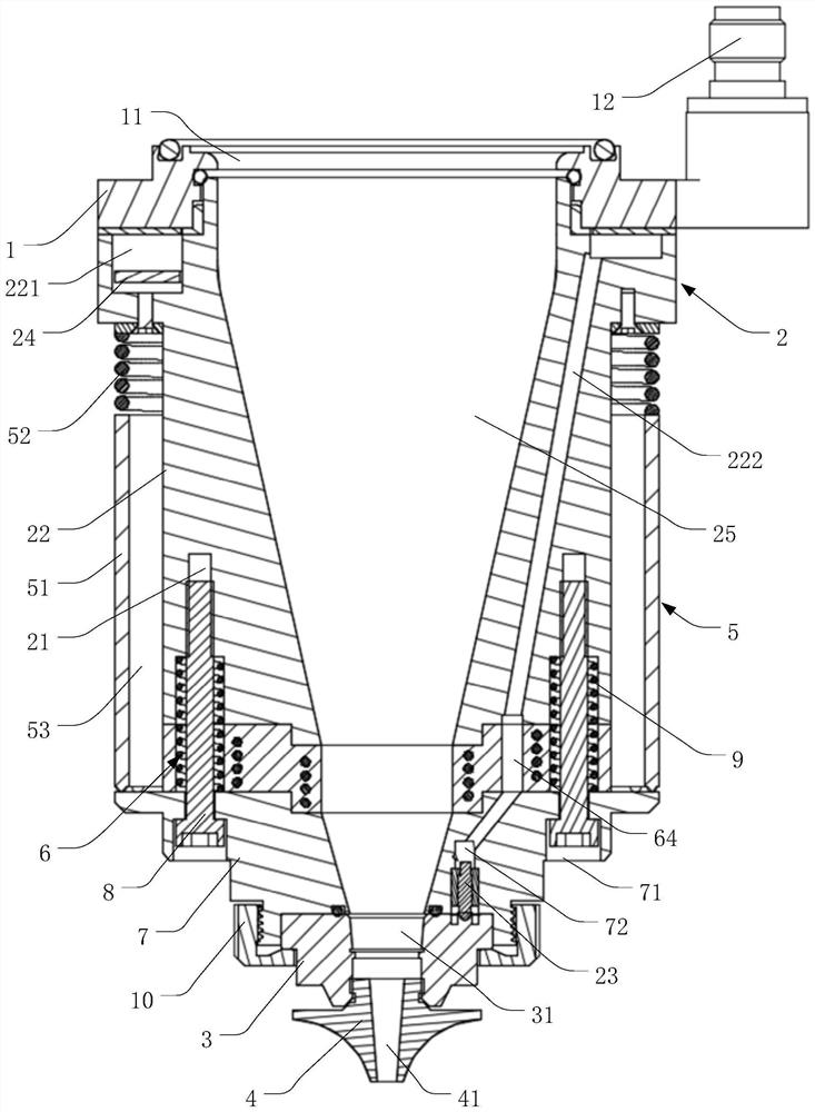
Figure 1 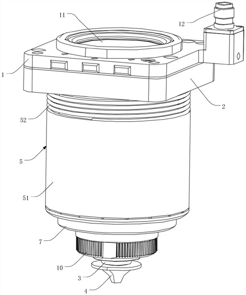
Figure 2 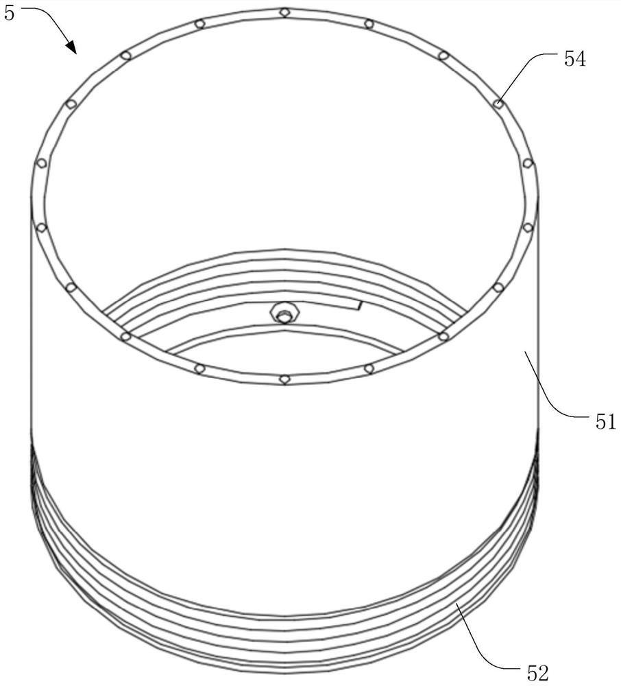
Figure 3
Abstract
Description
technical field
[0001] The invention belongs to the technical field of laser cutting, in particular to a capacitance sensing device and a laser cutting head. Background technique
[0002] With the continuous development of laser technology, the application of laser cutting technology is becoming more and more extensive. In the process of laser cutting, a capacitance value will be generated between the capacitive sensing device and the workpiece to be cut. Through the processing of this capacitance value, the distance between the capacitive sensing device and the surface of the workpiece can be guaranteed, thus solving the problem of the capacitive sensing device and the surface of the workpiece. The problem of collision between workpieces to be cut can be solved, and the quality of laser cutting can also be improved.
[0003] When the laser cutting head emits cutting laser light through the capacitive sensing device for laser cutting of the workpiece to be cut, the capaciti...
Examples
Embodiment Construction
[0026] In order to make the technical problems, technical solutions and beneficial effects solved by the present invention clearer, the present invention will be further described in detail below in conjunction with the accompanying drawings and embodiments. It should be understood that the specific embodiments described here are only used to explain the present invention, not to limit the present invention.
[0027] It should be understood that the orientation or positional relationship indicated by the terms "upper", "lower", "left", "right", "front", "rear", "middle", etc. are based on the orientation or position shown in the drawings The relationship is only for the convenience of describing the present invention and simplifying the description, but does not indicate or imply that the referred device or element must have a specific orientation, be constructed and operated in a specific orientation, and thus should not be construed as a limitation of the present invention. ...