
Cutting platform for glass fiber reinforced plastic products
A cutting platform, fiberglass technology, applied in the direction of metal processing, etc., can solve the problems of inability to cut fiberglass profiles, endanger the heart and lung function of workers, maintain the processing environment, etc., to achieve convenient axial movement, ingenious design, fast compression and smooth transportation Effect
Patent Information
- Authority / Receiving Office
- CN · China
- Patent Type
- Applications(China)
- Current Assignee / Owner
- Publication Date
- 2021-10-26
- Estimated Expiration
- Not applicable · inactive patent
Smart Images
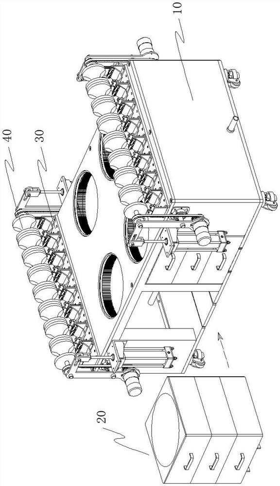
Figure 1 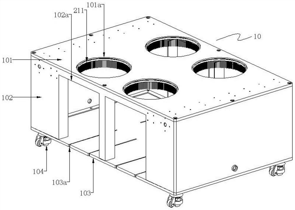
Figure 2 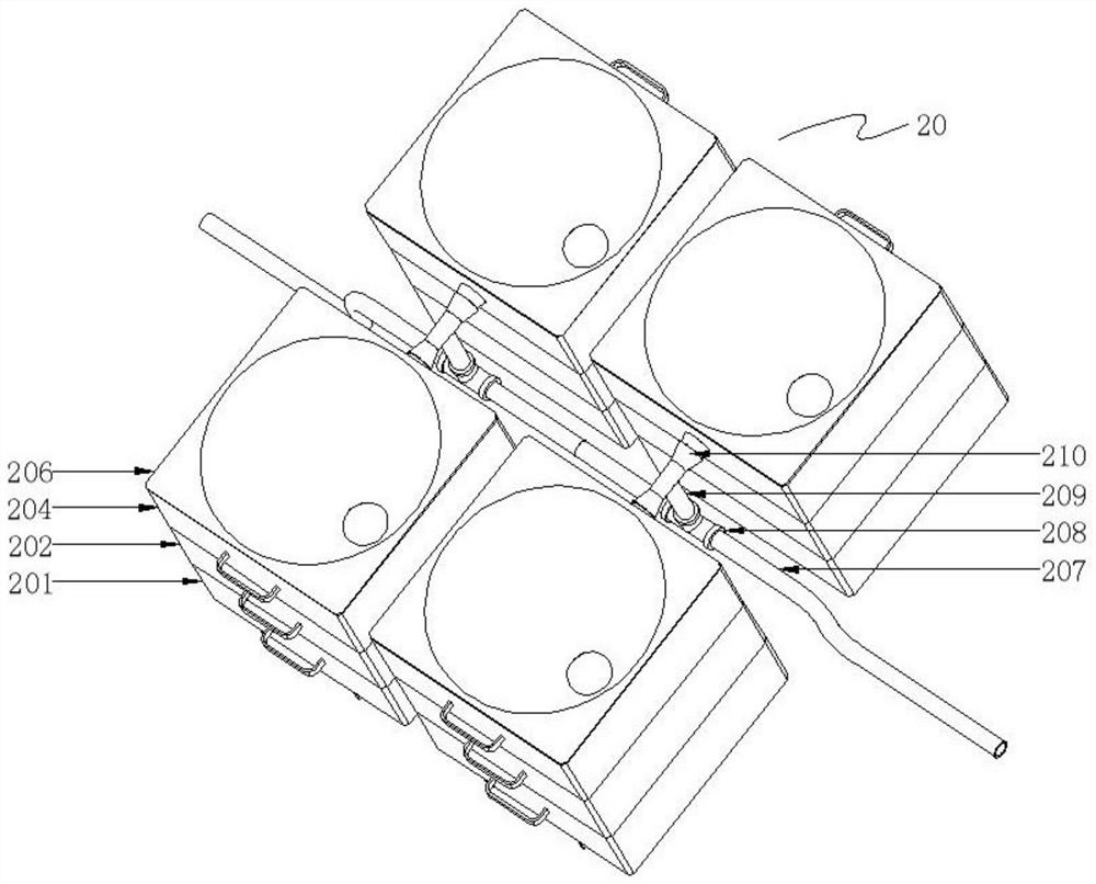
Figure 3
Abstract
Description
Technical field
[0001] The present invention relates to the technical field of FRP processing, and more particularly to a cutting platform for a glass steel article. Background technique
[0002] FRP (FRP) is also known as GFRP, namely fiber reinforced plastics, generally refers to glass fiber reinforced unsaturated polyester, epoxy resin and phenolic resin matrix. Reinforced plastics of a glass fiber or its products, referred to as glass fiber reinforced plastics, or glass steel, different from tempered glass.
[0003] At present, the glass steel profile produces a large amount of chips and dust during cutting and drilling, and a large amount of chips and dust are not conducive to workers to maintain processing environments, and they also seriously endanger the cardiopulmonary function of workers. Further, the existing adaptability of the existing device for the glass steel profile is poor and cannot be cut on a plurality of glass steel profiles. Inventive content
[0004] It i...
Examples
Embodiment Construction
[0030] In order to make the techniques, creative characteristics of the present invention, it is easy to understand that the present invention is further illustrated in connection with the specific embodiments.
[0031] like Figure 1 to 8 As shown, a cutting platform of a glass steel article includes a support assembly 10, a chip assembly 20, a positioning assembly 30, and a clamping assembly 40, wherein:
[0032] The support assembly 20 specifically includes a support top plate 101, a supporting cabinet 102, a supporting bottom plate 103, and a mutter 104, the support cabinet body 102 being a housing of a hollow long square structure without top and bottom surface, the support cabinet. The front and rear sides of the body 102 are provided with a uniformly spaced rectangular drawer port 102a, the support top plate 101, and the support bottom plate 103, respectively, at a top and bottom of the support cabinet 102, respectively, and the support top plate 101 is provided with a front...