

Environment-friendly multifunctional garbage treatment equipment based on garbage classification
A technology for waste treatment equipment and waste classification, which is applied in combustion types, lighting and heating equipment, combustion methods, etc. It can solve the problems of reducing the work efficiency of operators, wasting resources, and single internal structure, and improving convenience and speed. , reduce the waste of electricity resources and improve the effect of practicability
Patent Information
- Authority / Receiving Office
- CN · China
- Patent Type
- Applications(China)
- Current Assignee / Owner
- Publication Date
- 2021-11-23
- Estimated Expiration
- Not applicable · inactive patent
Smart Images
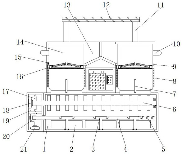
Figure 1 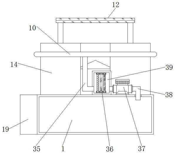
Figure 2 
Figure 3
Abstract
Description
technical field
[0001] The invention relates to the technical field of garbage disposal equipment, in particular to environmentally friendly multifunctional garbage disposal equipment based on garbage classification. Background technique
[0002] Garbage is solid waste generated in human daily life and production. Due to the large amount of discharge, complex and diverse components, and polluting, resourceful and social nature, it needs harmless, resourceful, reduction and socialized treatment. If it is not handled properly, it will pollute the environment, affect environmental sanitation, waste resources, destroy production and living safety, and disrupt social harmony. During the garbage disposal process, the garbage needs to be incinerated;
[0003] The internal structure of the existing garbage disposal equipment is relatively simple, and most of them directly squeeze the garbage into pieces and carry them to the designated location for incineration. This kind of operati...
Examples
Embodiment 1
[0041] Example 1, such as figure 1 , 5 The shown control assembly can drive the push rod 33 and the connecting rope 31 to move downward at the same time through the downward movement of the rectangular frame body 16 and the above parts during the working process, so that the push rod 33 can release the resistance to the push switch 27, and then through the connecting rope The downward movement of 31 can drive the protection bin 29 and the above parts to move downward to stretch the stay cord 28, and the push switch 27 can be stretched by the stay cord 28 so that it turns on the servo motor A18 for rotation work, and then the rectangular frame body 16 and the above parts continue to move down so that the connecting rope 31 drives the protection bin 29 to move, so that the protection bin 29 can stretch its internal coil spring 32. When the rectangular frame body 16 and the above parts are restored, they can pass The elastic recovery force of the coil spring 32 drives the protec...
Embodiment 2
[0042] Example 2, such as figure 1 , 4 When the turning assembly shown is in operation, the U-shaped rotating rod 20 can be driven to rotate by the servo motor B21, and the structural design of the U-shaped rotating rod 20 can make the U-shaped rotating rod 20 rotate against the connecting rod A4 and the tooth block 34 during the rotation process. Move at the same time, so that the connecting rod A4 stretches the high-temperature-resistant spring 5, and through the mutual meshing of the tooth block 34 and the gear A3, the gear A3 and the flip plate 2 can be driven to rotate at the same time during the movement of the tooth block 34, so as to turn over The plate 2 turns over the garbage at the bottom of the incinerator 1, and the continuous rotation of the servo motor B21 and the U-shaped rotating rod 20 can repeatedly pull and push the connecting rod A4 and the tooth block 34, so that the connecting rod A4 is opposite to the high temperature resistant spring. 5. Perform stret...
Embodiment 3
[0043] Example 3, such as figure 1 , 2 When the purification assembly shown is in operation, the smoke inside the garbage bin 14 can be sucked into the inside of the air intake pipe 10 through the air pump 37, transported to the inside of the connecting pipe 35 through the air intake pipe 10, and then discharged into the inside of the filter chamber 39. The filter board B36 provided inside the filter chamber 39 can filter harmful gases or impurities contained in the smog, and the filtered smog is discharged into the interior of the incineration chamber 1 through the exhaust pipe 38. Intake can again improve its incineration efficiency and reduce operator waiting time.
[0044] Working principle: The electrical components of the equipment are powered by batteries. First, the solar panel 12 is irradiated by sunlight, absorbs the sun's light energy and converts it into electrical energy. Charging, the solar panel 12 can provide power to add servo motor A18 and servo motor B21 a...