
Signal reading method and reading device of fingerprint imaging module
A technology for signal readout and imaging module, applied in character and pattern recognition, computer parts, computing, etc., can solve the problem that the performance of fingerprint imaging module needs to be improved, and achieve the effect of improving the utilization rate of material area and making full use of it.
Patent Information
- Authority / Receiving Office
- CN · China
- Current Assignee / Owner
- Publication Date
- 2022-03-25
Smart Images
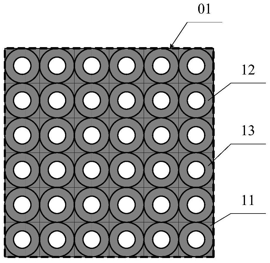
Figure 1 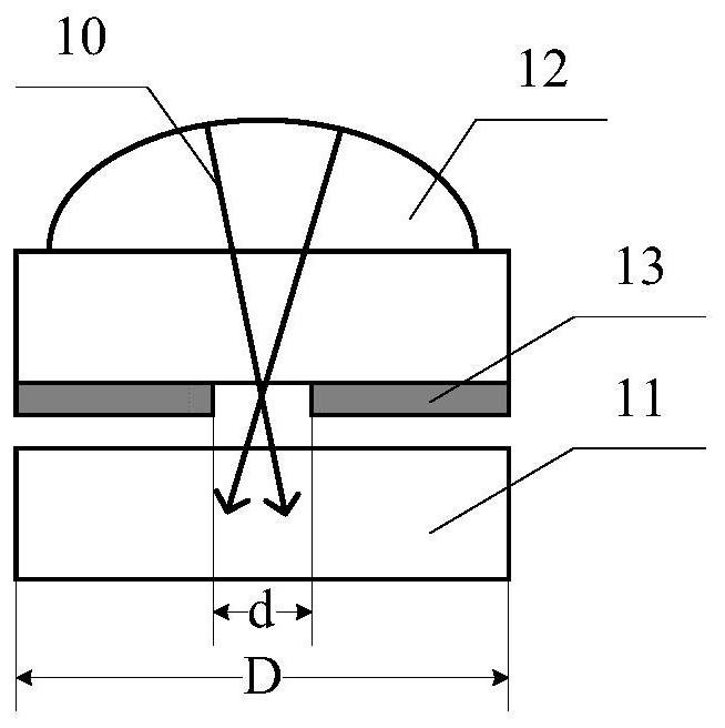
Figure 2 
Figure 3
Abstract
Description
technical field
[0001] The invention relates to the field of fingerprint identification, in particular to a signal readout method and a readout device of a fingerprint imaging module. Background technique
[0002] The fingerprint identification technology collects the fingerprint image of the human body through the fingerprint imaging module, and then compares it with the existing fingerprint imaging information in the fingerprint identification system to realize identity identification. Due to the convenience of use and the uniqueness of human fingerprints, fingerprint recognition technology has been widely used in various fields, such as: public security bureaus, customs and other security inspection fields, building access control systems, and consumer products such as personal computers and mobile phones, etc.
[0003] The imaging methods of the imaging module used in the fingerprint identification technology include optical, capacitive, ultrasonic and other technologies...
Examples
Embodiment Construction
[0049] It can be seen from the background art that the performance of the fingerprint imaging module provided with microlenses needs to be improved in the prior art. Now combine the structure of the fingerprint imaging module with microlens to analyze its performance:
[0050] refer to figure 1 and figure 2 ,in figure 1 It is a top view structure diagram of a fingerprint imaging module; figure 2 yes figure 1 The schematic diagram of the cross-sectional structure of a single pixel unit in the fingerprint imaging module shown.
[0051] The fingerprint imaging module includes: pixel units 11 arranged in an array to form a pixel array 01, the pixel units 11 are used to collect signal light 10; microlenses 12, the microlenses correspond to each other one by one is located above the pixel unit 11 , and the microlens is used to converge the signal light 10 .
[0052] In order to interfere with the light collection of the signal 10 by stray light, it is necessary to select an ...