
QS type submersible electric pump transportation equipment
A technology of transportation equipment and submersible electric pump, which is applied in the field of transportation, can solve the problems of inconvenient transportation, single function, and poor protection of the pump body, and achieve the effects of improving dryness and sanitation, reducing erosion, and making it easy to take out the pump body
Patent Information
- Authority / Receiving Office
- CN · China
- Patent Type
- Applications(China)
- Current Assignee / Owner
- Publication Date
- 2022-06-03
- Estimated Expiration
- Not applicable · inactive patent
Smart Images
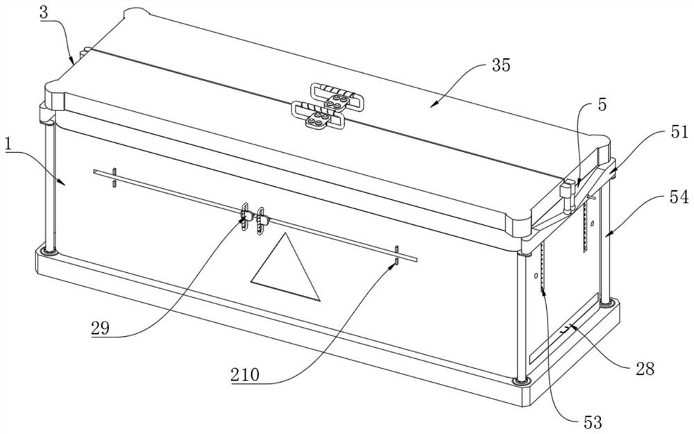
Figure 1 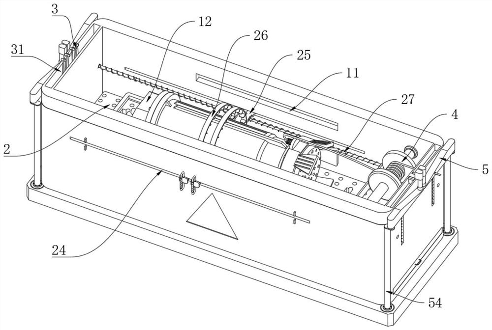
Figure 2 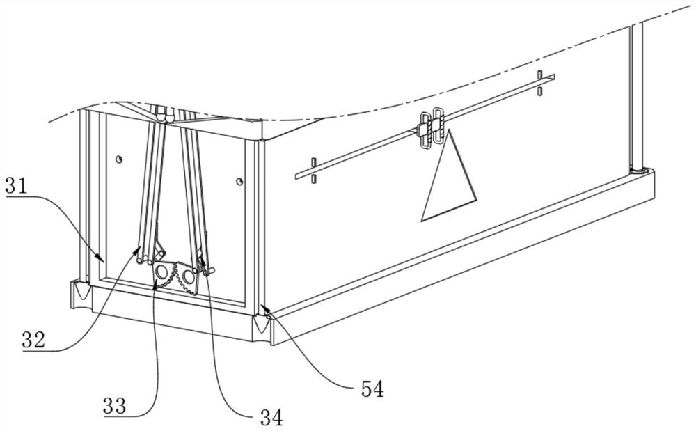
Figure 3
Abstract
Description
technical field
[0001] The invention relates to the field of transportation, in particular to a QS type submersible electric pump transportation equipment. Background technique
[0002] "QS type submersible pump" is a water-lifting tool with reliable performance, integrated machine and pump, and submerged operation. It is widely used in irrigation and drainage of farmland, water supply and drainage systems of industrial and civil construction sites, fountain engineering, and hilly and mountainous areas. Water diversion, drainage of low-lying areas, etc.
[0003] During the transfer and transportation of existing submersible pumps, the commonly used appliances are relatively common and have single functions, which are not only inconvenient for safe transportation, but also have poor protection for the pump body. Therefore, the present invention proposes a method that can solve the above problems. The problem is the transport equipment that can be used for portable transport ...
Examples
Embodiment 1
[0030] Please refer to Figure 1 to Figure 4 As shown, the left side of the transport box 1 is provided with a lifting mechanism 3, and the lifting mechanism 3 includes an installation cavity 31, a linkage slat 32, a fan-shaped toothed plate 33, a jacking shaft 34, a case cover 35, and the transport box 1 The interior of the left side is provided with an installation cavity 31, and the inner wall of the installation cavity 31 is symmetrically hinged with linkage slats 32, the upper end of the linkage slats 32 is hinged with a box cover 35, and the right side of the box cover 35 is slidably connected to the transport box 1, the side of the linkage slats 32 close to each other is fixedly connected with a fan-shaped gear plate 33, and the right side of the fan-shaped gear plate 33 is fixedly connected with a jacking shaft 34, and the upper end of the jacking shaft 34 is fixedly connected to the On the outside of the left side of the carrier plate 21 , the upper end of the jacking...
Embodiment 2
[0033] Please refer to Figure 5 and Figure 7As shown, the inner right side of the transport box 1 is provided with a take-up mechanism 4, the take-up mechanism 4 includes a take-up wheel 41, a wire cavity 42, a drainage groove 43, a hand handle 44, and the right side of the transport box 1 A take-up wheel 41 is connected in rotation, and the back side of the take-up wheel 41 is fixedly connected with a hand crank 44, and the hand crank 44 extends to the outside of the back side of the transport box 1, and the right side of the take-up wheel 41 is provided with a wire circle. Cavity 42, the wire round cavity 42 is fixedly connected on the right side wall of the transport box 1, the below of the wire round cavity 42 is provided with a drainage groove 43 on the right side wall of the transport box 1, the left and right sides of the transport box 1 All are provided with reinforcing mechanism 5, and reinforcing mechanism 5 comprises wedge-shaped pressing plate 51, abutment shaft...
Embodiment 3
[0036] Please refer to Figure 1 to Figure 7 As shown, a QS type submersible electric pump transportation equipment includes a transportation box 1, and a scraping mechanism 2 is arranged inside the transportation box 1. The scraping mechanism 2 includes a carrier plate 21, a paddle 22, a support frame 23, an opening Chute 24, sliding connecting plate 25, cleaning ring 26, spring bar 27, stopper 28, pulling ear 29, magnetic piece 210, the bottom of transport case 1 interior is provided with carrying plate 21, and the right side of carrying plate 21 rotates Connected to the front and rear sides of the transport box 1, a paddle 22 is arranged under the carrier board 21, a plug 28 is fixedly connected to the right end of the paddle 22, and a support frame 23 is fixedly connected to the upper surface of the carrier board 21. The front and rear sides of the transport box 1 are symmetrically provided with opening chute 24, the left and right sides of the opening chute 24 are fixedly...