
Optical pickup-use object lens, optical pickup and optical disk unit
一种拾波器、光学的技术,应用在光束引导装置、光学、光学元件等方向,能够解决聚焦衍射极限、很难激光等问题,达到减少部件数的效果
Patent Information
- Authority / Receiving Office
- CN · China
- Patent Type
- Patents(China)
- Current Assignee / Owner
- Publication Date
- 2007-01-17
- Estimated Expiration
- Not applicable · inactive patent
Smart Images
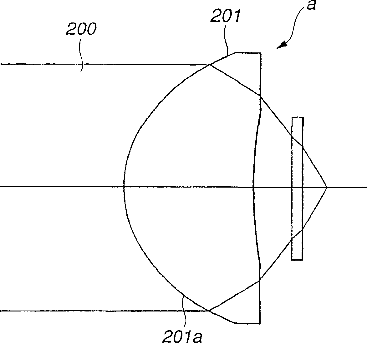
Figure 1 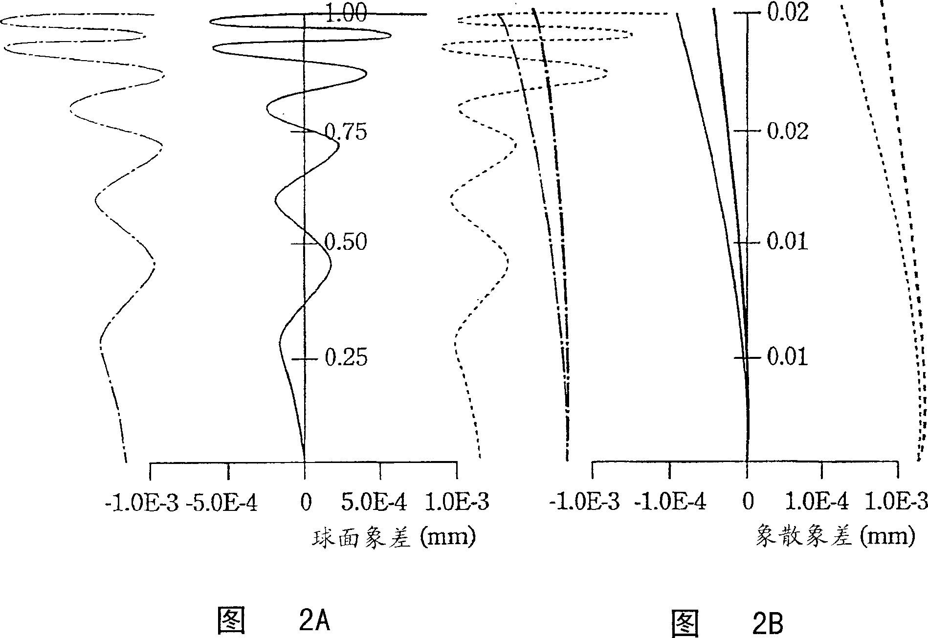
Figure 2 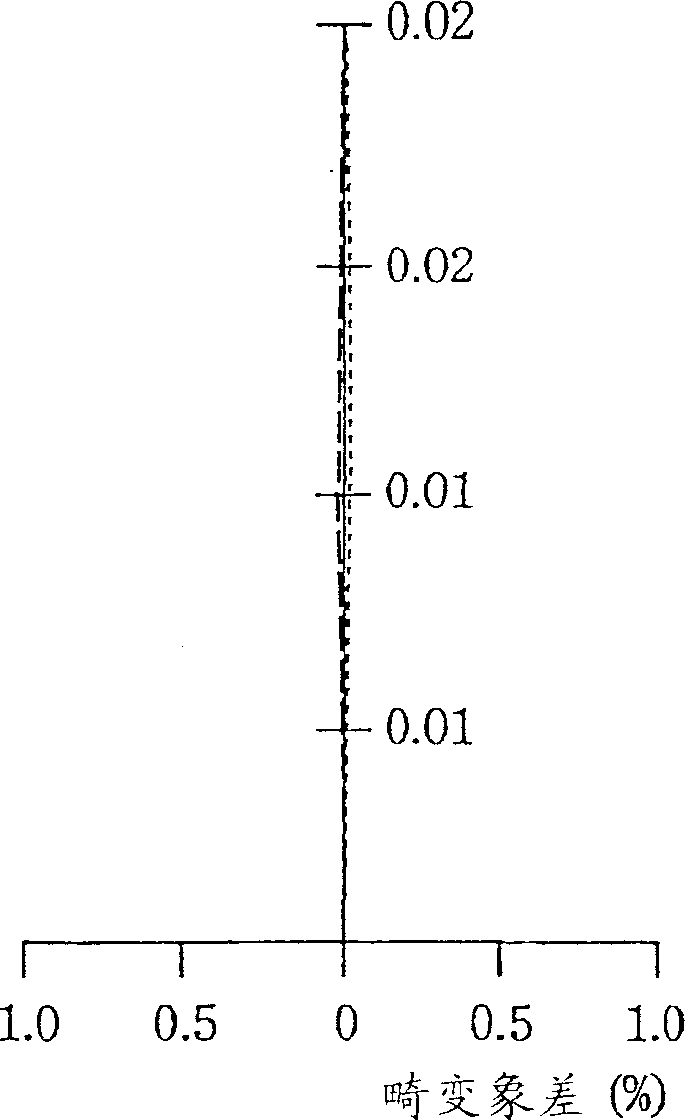
Figure 3
Abstract
Description
technical field
[0001] The present invention relates to an objective lens used in an optical pickup device for irradiating an optical recording medium with a beam of laser light or the like to record information and reproduce the information recorded on the optical recording medium, and an optical pickup using the objective lens The device relates to an optical disc device, more specifically, an objective lens capable of focusing light beams to a diffraction limit on a recording surface of an optical recording medium, an optical pickup device using the objective lens, and an optical disc device. Background technique
[0002] As an information recording medium, a high recording density non-contact optical recording medium is currently used. In an optical recording medium, information is recorded by irradiating a light beam, such as laser light, on the recording surface, and the recorded information can be reproduced. Such an optical recording medium is widely used as an opti...
Examples
Embodiment 2
[0184] The objective lens 15 of embodiment 2 has the 1st lens group GR1 that is made up of the 1st lens L1 and the 2nd lens group GR2 that is made up of the 2nd lens L2, and this 1st lens L1, by having the refractive surface S 2r is the base plane and forms the diffraction plane S 2d and the composite surface S 2 The second lens L2 is a single-piece aspheric glass molded lens with large magnification. A protective layer 30 made of polycarbonate is disposed between the second lens L2 and the image surface (recording layer of the optical disc 100).
[0185] The numerical values of the constituent lenses of Example 2 are listed in Table 3 below.
[0186] r i
d i
r 1 =∞
d 1 =1.00
resin
r 2 =7.650
d 2 =0.20
r 3 =1.337
d 3 =1.60
LAH53
r 4 =6.486
d 4 =0.74
r 5 =∞
d 5 =0.1
Image plane = ∞
[0187] Embodiment 2, because the 1st ...
Embodiment 3
[0193] The objective lens 15 of embodiment 3 has the 1st lens group GR1 made up of the 1st lens L1 and the 2nd lens group GR2 made up of the 2nd lens L2, and this 1st lens L1, by having the refraction surface S 2r A synthetic resin layer 18 is laminated as a base surface, and a diffraction surface S is formed on the surface of the synthetic resin layer 18. 2d Composite surface S 2 The second lens L2 is a single piece of aspheric glass molded lens with large magnification. A protective layer 30 made of polycarbonate is disposed between the second lens L2 and the image surface (recording layer of the optical disc 100).
[0194] The numerical values of the constituent lenses of Example 3 are listed in Table 5 below.
[0195] r i
d i
r 1 =∞
d 1 =1.00
SBSL7
r 2r =7.750
d 2 =0.01
r 2d =7.750
d 3 =0.20
resin
r 3 =1.337
d 4 =1.60
LAH53
r 4 =6.486
d 5 =0.74
...
Embodiment 5
[0211] The objective lens 15 of embodiment 5 has the 1st lens group GR1 made up of the 1st lens L1 and the 2nd lens group GR2 made up of the 2nd lens L2, and this 1st lens L1, by having the refraction surface S with the 2nd surface 2r is the base plane and forms the diffraction plane S 2d and the composite surface S 2 The second lens L2 is a single-piece aspheric glass molded lens with large magnification. A protective layer 30 made of polycarbonate is disposed between the second lens L2 and the image surface (recording layer of the optical disc 100).
[0212] The numerical values of the constituent lenses of Example 5 are listed in Table 9 below.
[0213] r i
d i
r 1 =∞
d 1 =1.00
resin
r 2 =7.650
d 2 =3.00
r 3 =1.337
d 3 =1.60
LAH53
r 4 =6.486
d 4 =0.74
r 5 =∞
d 5 =0.1
polycarbonate
Image plane = ∞
[0214] The objective lens 15 of ...