
Drilling bit without resharpening, non-resharpening blade, and drilling bit main body
A drill bit and blade technology, applied in drilling/drilling equipment, shovel drill, drill repair, etc., can solve the problems of insufficient alignment accuracy, difficulty in firmly holding the blade 5, and difficulty in adhering to it, and achieve the goal of maintaining the accuracy of shaft vibration Effect
Patent Information
- Authority / Receiving Office
- CN · China
- Patent Type
- Applications(China)
- Current Assignee / Owner
- Publication Date
- 2004-09-08
- Estimated Expiration
- Not applicable · inactive patent
Smart Images
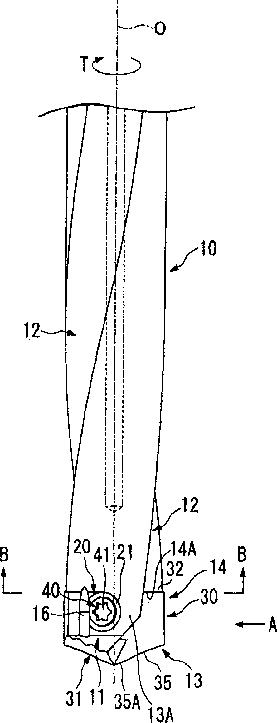
Figure 1 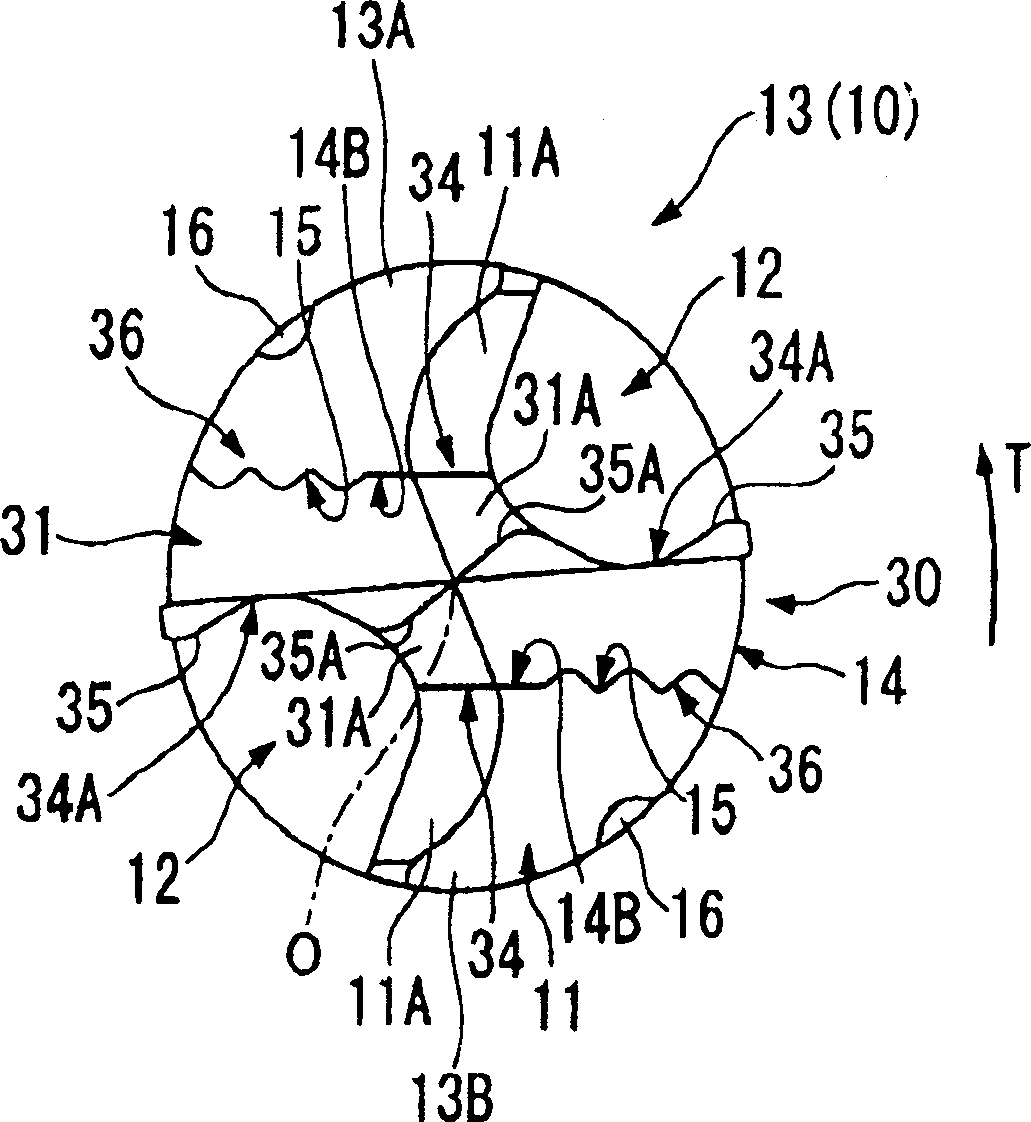
Figure 2 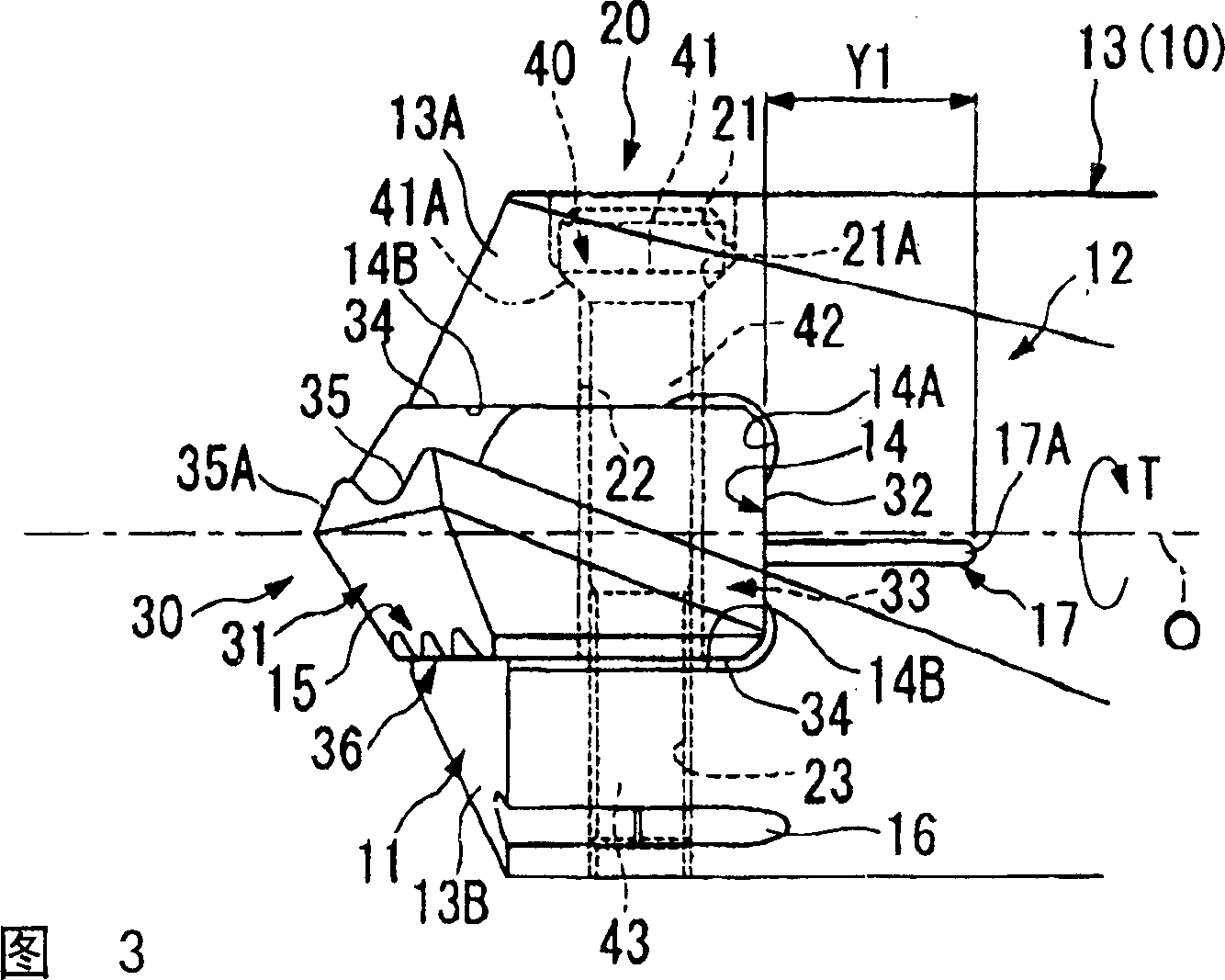
Figure 3
Abstract
Description
technical field
[0001] The present invention relates to a throw-away type that detachably mounts a substantially flat throw-away insert (hereinafter referred to as insert) having a cutting edge at the front end to a groove-shaped insert mounting seat formed at the front end of the drill body. drill. Background technique
[0002] An example of such throwaway drills is disclosed in Japanese Unexamined Patent Publication No. 11-197923, for example. In this kind of drill, a circular hole is formed on the bottom surface of a groove-shaped insert mounting seat opened on the front end surface of the drill body, and a hole that can be inserted is provided on the rear end surface of a substantially flat blade mounted on the insert mounting seat. to the shaft portion inside the above-mentioned circular hole. Simultaneously, by inserting the shaft portion into the circular hole, the engaging member protruding from the inner periphery of the circular hole is engaged with the notch for...
Examples
Embodiment Construction
[0052] Embodiments of the present invention will be described below with reference to the drawings.
[0053] Figure 1 to Figure 5 It represents the first embodiment of the present invention.
[0054] The drill body 10 of the throwaway drill of this embodiment is reduced in diameter with respect to the drill pipe tail (not shown) integrally formed on its rear end side, and as a whole constitutes a drill body 10 that rotates around the axis O and rotates around the axis O. Centered multistage cylinder.
[0055] A pair of chip discharge grooves 12 opened on the front end surface 11 of the drill body 10 are formed on the outer periphery of the front end side portion of the drill body 10, and the discharge grooves 12 are on mutually opposite sides of the clamping axis O so as to move toward the axis O. The rear end side of the drill bit is twisted backward in the direction of rotation T of the drill to form a helical shape.
[0056] In addition, on the front end portion 13 of t...