
Oppositely clamped type direct-acting valve
A direct-acting valve and clamp-type technology, which is applied in the direction of lifting valve, valve detail, safety valve, etc., can solve the problems of increased manufacturing cost and bulkiness, and achieve the effects of reduced manufacturing cost, overall weight reduction and size reduction
Patent Information
- Authority / Receiving Office
- CN · China
- Patent Type
- Applications(China)
- Current Assignee / Owner
- Publication Date
- 2007-06-20
Smart Images
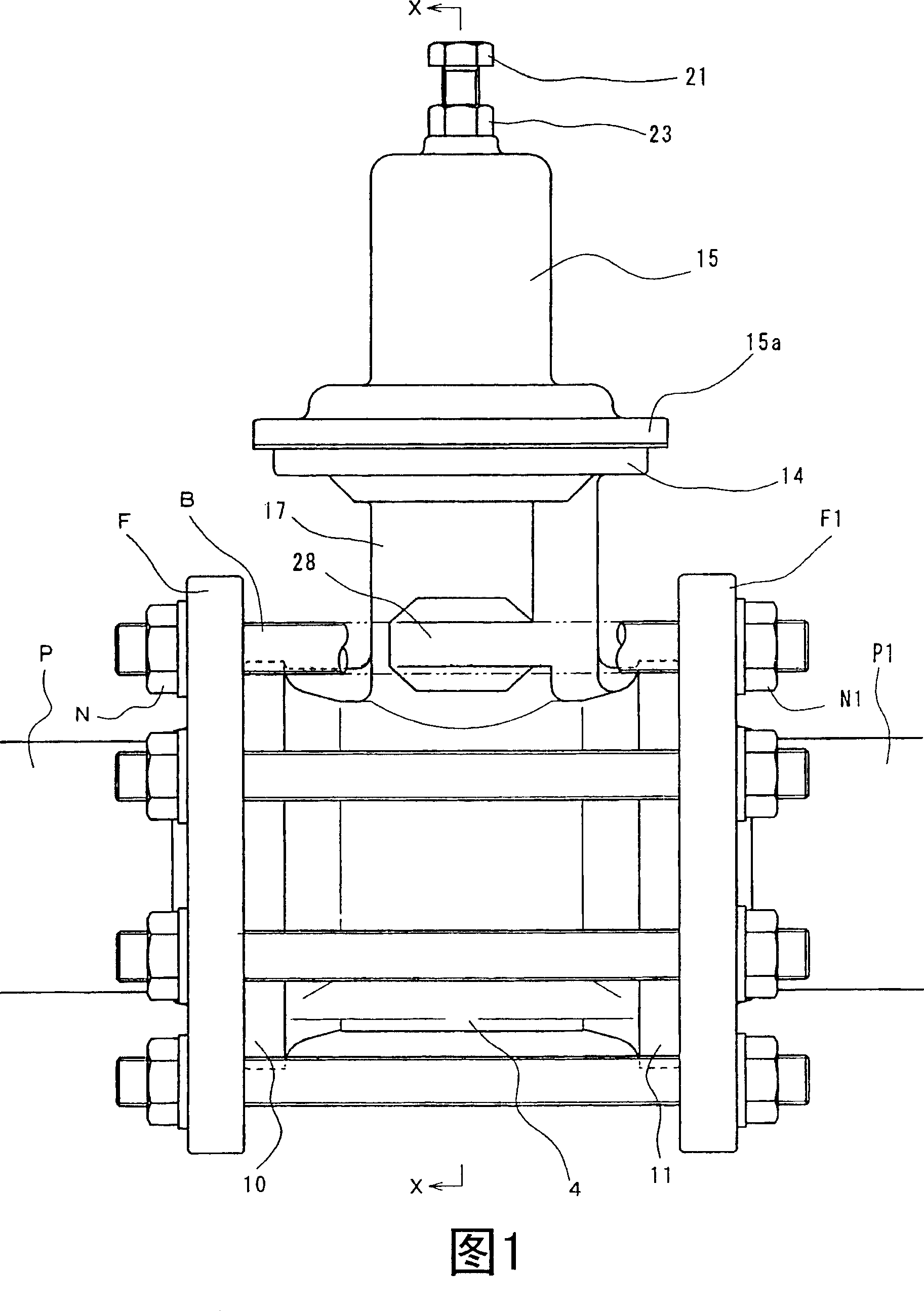
Figure 1 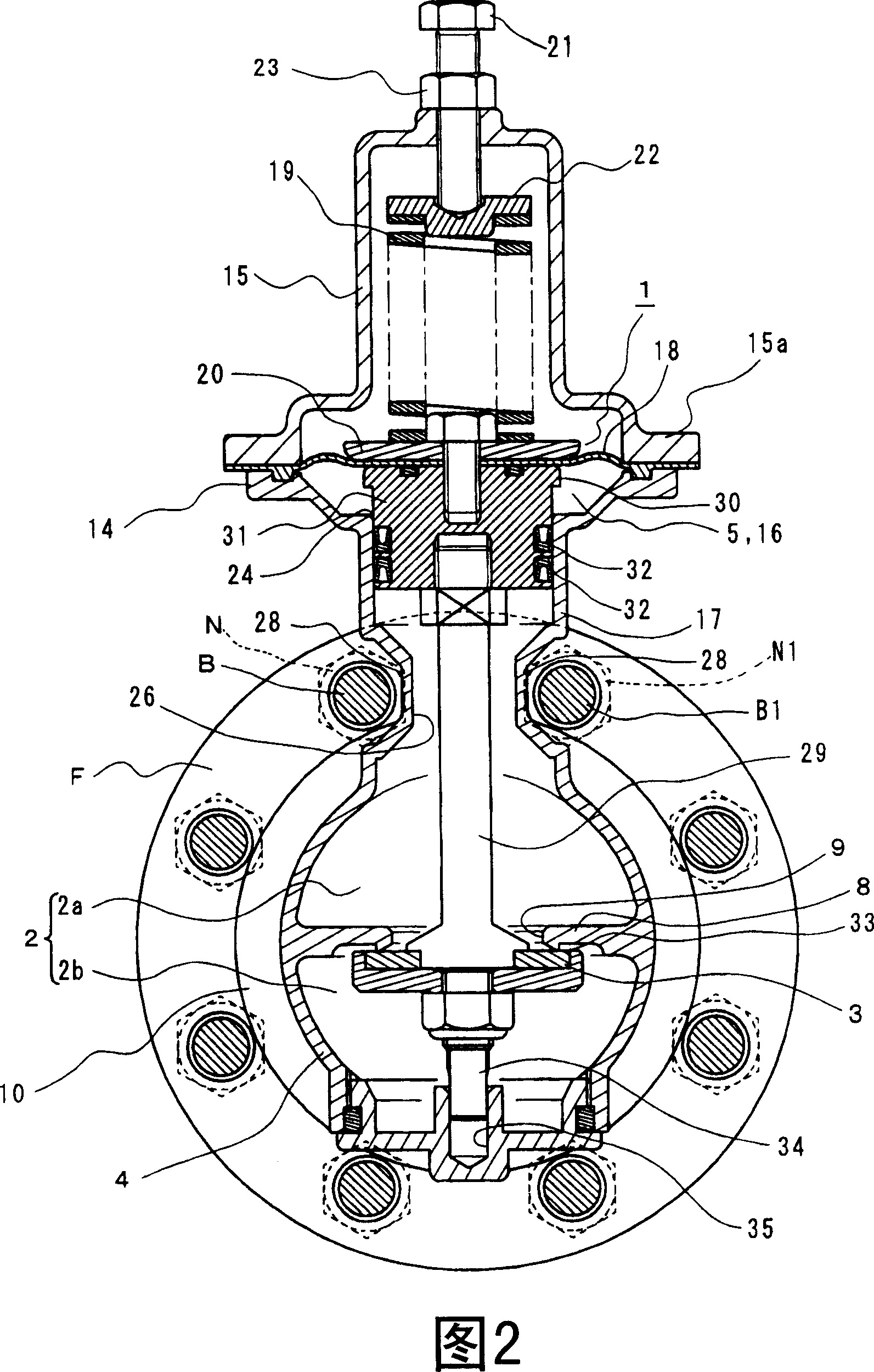
Figure 2 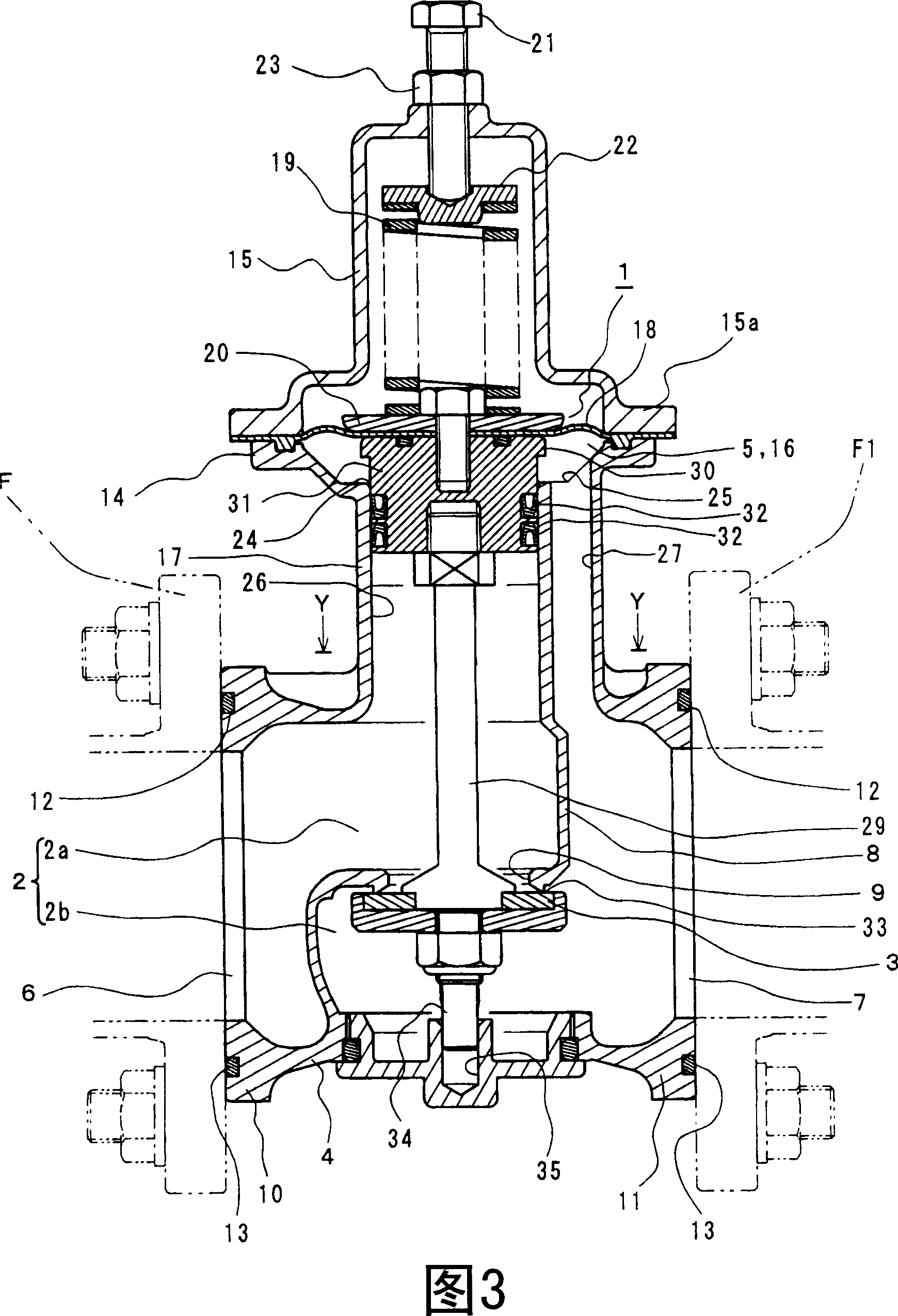
Figure 3
Abstract
Description
technical field
[0001] The present invention relates to a wafer-type direct-acting valve in which direct-acting valves such as pressure regulating valves (such as pressure reducing valves), solenoid valves, and constant water level valves are clamped between pipe flanges and bolts through the pipe flange and the like. Background technique
[0002] Conventionally, there is a wafer type valve in which the valve box is located between pipe flanges, and the pipe flanges are fastened by bolts and nuts. As this type of valve, there are single plate check valves and flangeless butterfly valves. In these valves, a thin disc-shaped valve body oscillates or rotates within a thin cylindrical valve box, opening and closing a flow path through which fluid flows linearly. These valves are relatively simple in structure and operation (for example, see Non-Patent Document 1).
[0003] On the other hand, there are also direct acting valves in which the valve body is connected to the drive...
Examples
Embodiment Construction
[0019] Next, an example as an embodiment of the present invention will be described based on the drawings.
[0020] Fig. 1 is a front view of a piping state of a wafer type direct acting valve.
[0021] Fig. 2 is a cross-sectional view taken along line X-X of Fig. 1 .
[0022] Fig. 3 is a longitudinal sectional view taken along line X-X in Fig. 1 .
[0023] FIG. 4 is an enlarged cross-sectional view taken along line Y-Y of FIG. 3 with part omitted.
[0024] The valve is a direct-acting valve, which includes a driving part 1 that operates when primary pressure or secondary pressure is detected, and a valve body 3 that communicates with (or is connected to) the driving part 1 and is manipulated to open and close flow path 2. The valve shown is a direct acting pressure reducing valve.
[0025] The structure of the direct acting pressure reducing valve is as follows. The valve box (or valve chamber) 4 includes the flow path 2 (including the primary flow path 2a and the second...