
Optical apparatus with rotational operating member
a technology of rotating operating member and optical apparatus, which is applied in the direction of optics, mountings, instruments, etc., can solve the problems of operating quality, large force required to perform the zooming operation, and actual composition to differ from an intended composition, so as to improve the operating quality of the rotational operating member and low cost
Patent Information
- Authority / Receiving Office
- US · United States
- Patent Type
- Patents(United States)
- Current Assignee / Owner
- Publication Date
- 2019-09-10
Smart Images
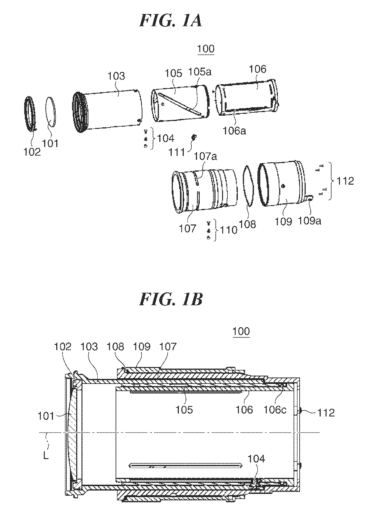
Figure 1 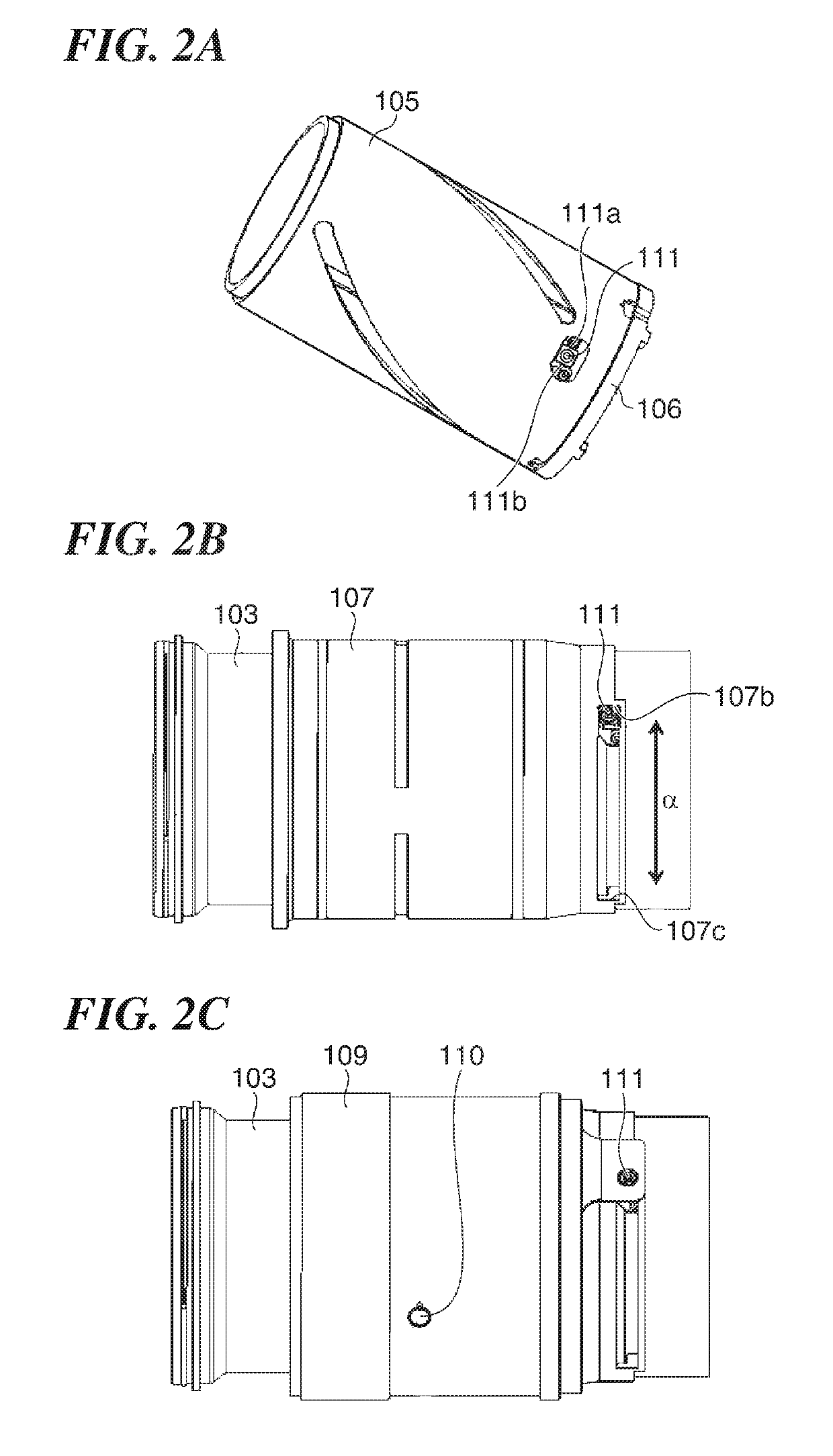
Figure 2 
Figure 3
Abstract
Description
BACKGROUND OF THE INVENTIONField of the Invention
[0001] The present invention relates to an optical apparatus with a rotational operating member.Description of the Related Art
[0002] When a zooming operation is performed with an image pickup apparatus, which is equipped with a lens barrel having a heavy zoom lens group, pointing upward or downward, unintended zooming may occur due to lens' own weight, causing an actual composition to differ from an intended composition. To prevent such unintended zooming, there is known an arrangement in which an operating member for performing a zooming operation is urged using an elastic member to apply torque acting as a brake. However, when the operating member is urged using the elastic member, large force is required to perform the zooming operation. Particularly when the heavy zoom lens group is driven using a cam mechanism in zooming, a problem arises due to operating quality compromised in an area where large operating force is required such a...
Examples
Embodiment Construction
[0021]Hereafter, embodiments of the present invention will be described in detail with reference to the drawings. In the following description of the embodiments, a lens barrel which an image pickup apparatus such as a digital camera has is taken as an example of an optical apparatus according to the present invention, but the optical apparatus according to the present invention is not limited to this.
[0022]A description will now be given of the first embodiment of the present invention. FIG. 1A is an exploded perspective views showing a lens barrel 100 according to the first embodiment of the present invention. FIG. 1B is a cross-sectional view showing the lens barrel 100. The lens barrel 100 has a lens group 101, a lens holding member 102, a holding cylinder 103, engaging members 104, a guide member 105, a straight-ahead guide member 106, a fixing member 107, a pressing member 108, and a rotational operating member 109 (hereafter referred to “the operating member 109”).
[0023]The l...