
Sensor
Patent Information
- Authority / Receiving Office
- US · United States
- Current Assignee / Owner
- Publication Date
- 2020-03-03
Smart Images
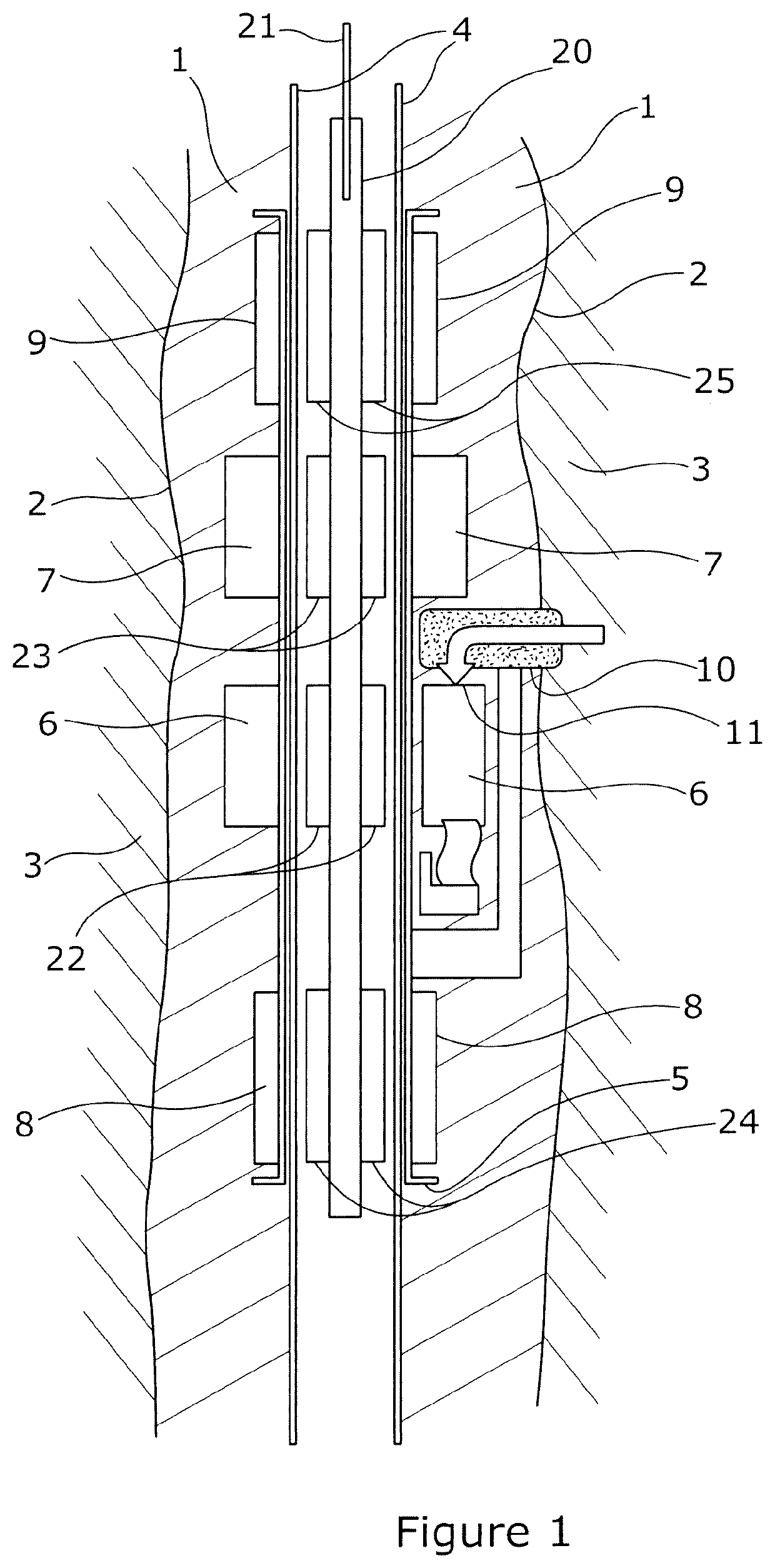
Figure 1 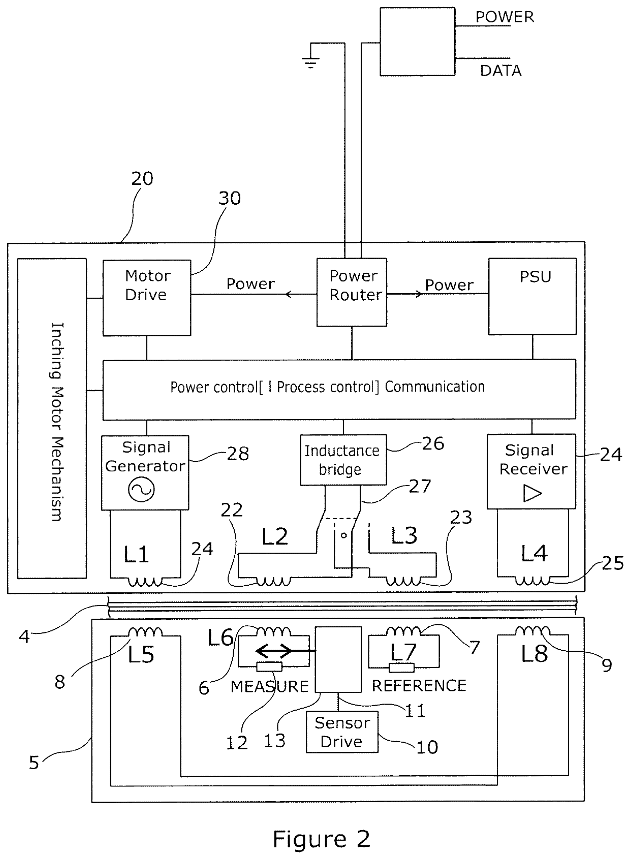
Figure 2 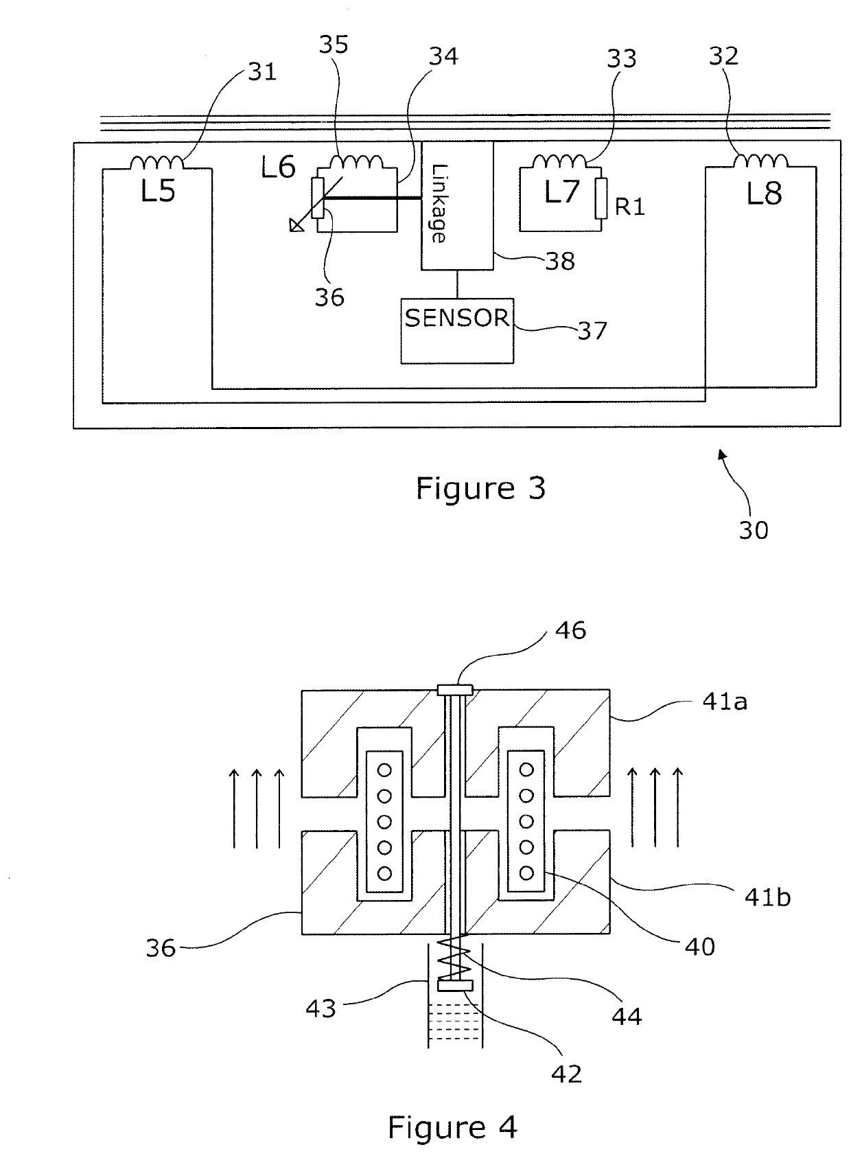
Figure 3
Abstract
Description
FIELD OF THE INVENTION
[0001] This invention relates to sensors for measuring physical characteristics such as pressure or temperature. More particularly, it relates to sensors that measure such characteristics in hard to access and inhospitable locations such as within an oil or gas well.BACKGROUND OF THE INVENTION
[0002] When drilling for oil or gas, either in an exploratory well, or in a production well, it is often desirable to be aware of various physical characteristics of the geology surrounding a wellbore. For example, it is often helpful to be able to measure the temperature and / or pressure that exists at differing depths or distances along the wellbore.
[0003] A wellbore typically comprises of a hole drilled into the earth, into which is inserted a metal sectional tube, pipe, or casing etc., the resulting gap between the outside of the casing and the underlying geology (typically rock) being generally filled with a cement mixture which acts to restrict fluid movement and also ac...
Examples
Embodiment Construction
[0050]FIG. 1 shows a physical arrangement of the key components of an embodiment of the invention, and how they may be deployed in a wellbore. The Figure is a sectional profile view through the wellbore.
[0051]A wellbore 1, having walls 2 has been drilled into rock 3. A metal pipe or casing 4 is positioned within the wellbore 1. In the gap between the outside of the pipe 4 and the walls 2 a first module 5 is positioned, typically when installing pipe 4. The module 5 comprises, inter alia, a measurement coil 6, a reference coil 7, and a pair of alignment coils 8, 9. The coils 6, 7, 8 and 9 are all wound around the pipe 4. A mechanical pressure sensor 10 has an input that is subject to pressure variations within the rock 3, and converts these pressure variations to movement of its output shaft 11. The output shaft is connected to a the measurement coil 6, such that movement of the shaft 11 results in movement of the coil 6 axially along the pipe 4.
[0052]The measurement and reference co...