
Method for producing a rotor blade
a rotor blade and rotor blade technology, which is applied in the direction of turbines, efficient propulsion technologies, machines/engines, etc., can solve the problems of difficult to achieve a wall thickness of 1 mm, complex geometries can be produced in the interior of the blade, and the known 3-d printing method can achieve the reduction of component strength, improve the efficiency and power of gas turbines, and reduce the thickness of the blade airfoil
Patent Information
- Authority / Receiving Office
- US · United States
- Patent Type
- Patents(United States)
- Current Assignee / Owner
- Publication Date
- 2020-06-02
Smart Images
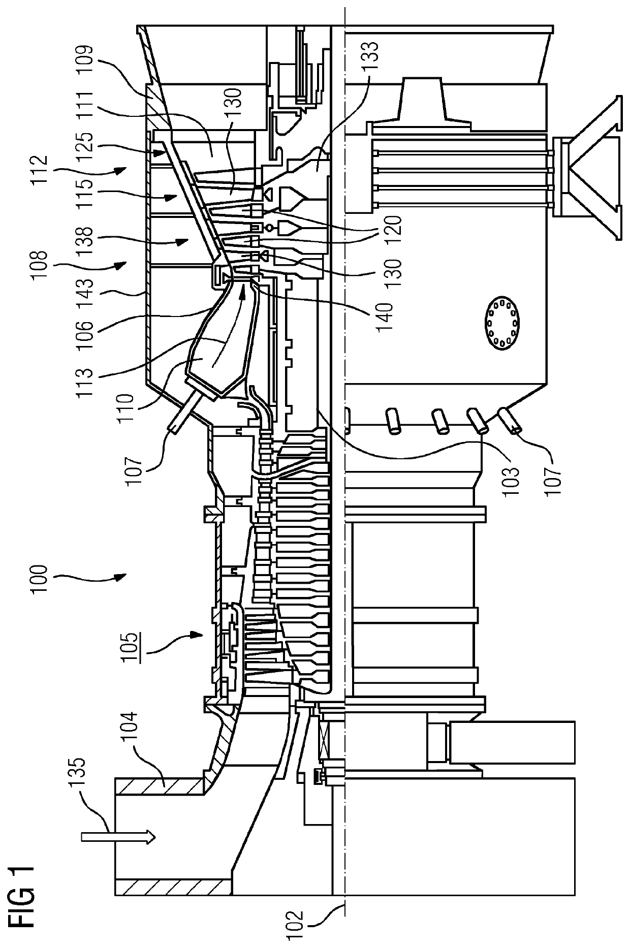
Figure 1 
Figure 2 
Figure 3
Abstract
Description
CROSS REFERENCE TO RELATED APPLICATIONS
[0001] This application is the US National Stage of International Application No. PCT / EP2015 / 075384 filed Nov. 2, 2015, and claims the benefit thereof. The International Application claims the benefit of European Application No. EP14196293 filed Dec. 4, 2014. All of the applications are incorporated by reference herein in their entirety.FIELD OF INVENTION
[0002] The invention relates to a method for producing a rotor blade for a gas turbine, the blade having a fastening region and a platform, on which a blade airfoil ending in a blade tip is arranged. It furthermore relates to a rotor blade of this kind.BACKGROUND OF INVENTION
[0003] Rotor blades of the abovementioned type are used in gas turbines to convert the energy of a hot gas flow into rotational energy. They typically have a blade airfoil, which is penetrated by cavities for carrying cooling air and which is fastened on a “platform”. Adjoining the platform there is a fastening region for fast...
Examples
Embodiment Construction
[0027]In all the figures, identical parts are provided with the same reference signs.
[0028]FIG. 1 shows a gas turbine 100 in a partial longitudinal section. A turbine is a continuous flow machine which converts the internal energy (enthalpy) of a flowing fluid (liquid or gas) into rotational energy and ultimately into mechanical driving energy.
[0029]In the interior, the gas turbine 100 has a rotor 103, which is mounted so as to rotate about an axis of rotation 102 (axial direction) and which is also referred to as a turbine rotor. Situated one after the other along the rotor 103 are an intake casing 104, a compressor 105, a toroidal combustion chamber 110, in particular an annular combustion chamber 106, having a plurality of coaxially arranged burners 107, a turbine 108 and the exhaust casing 109.
[0030]The annular combustion chamber 106 communicates with an annular hot gas duct 111. There, four turbine stages 112 arranged in series, for example, form the turbine 108. Each turbine s...