
Upright for a shading system, removable flange of the upright and corresponding coupling means
a shading system and upright technology, applied in the direction of door/window protective devices, building components, constructions, etc., can solve the problems of increasing production costs, complicated assembly, and slow assembly speed, and is not practical nor easy to screw screws inside the threaded holes
Patent Information
- Authority / Receiving Office
- US · United States
- Patent Type
- Patents(United States)
- Current Assignee / Owner
- Publication Date
- 2021-02-16
Smart Images
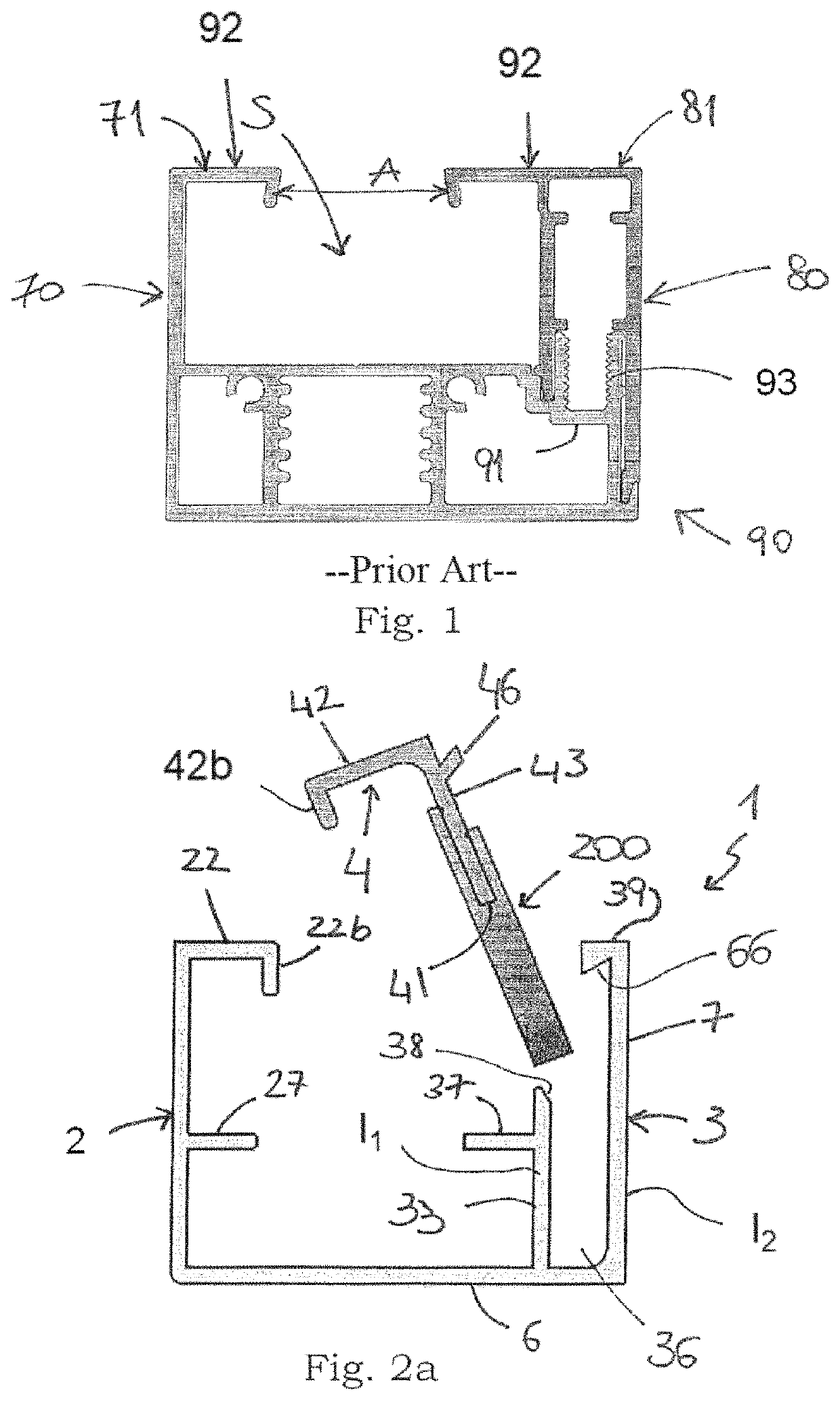
Figure 1 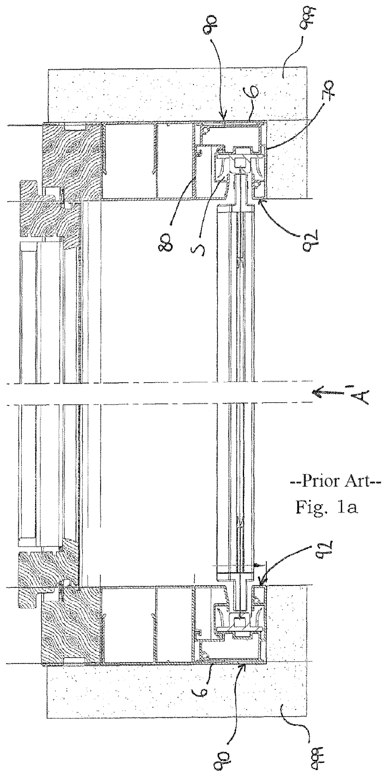
Figure 2 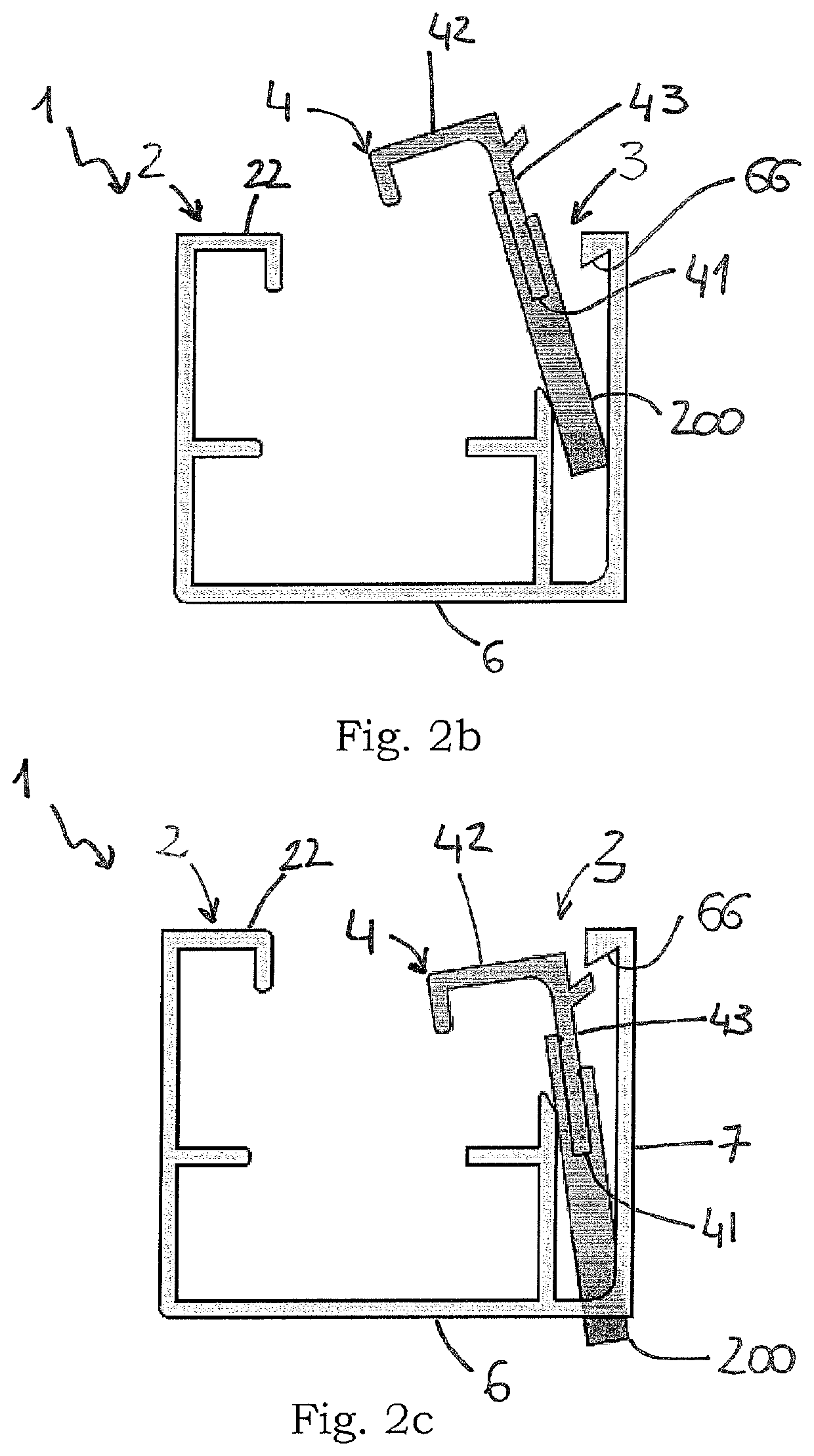
Figure 3
Abstract
Description
FIELD OF APPLICATION
[0001] The present invention relates to an upright comprising two flanks between which a profiled element for a shading system can be inserted, said profiled element being intended to receive the edge of a shading screen which extends as far as the profiled element of an oppositely arranged upright.
[0002] The present invention also relates to a removable flange of the aforementioned upright, designed to allow mounting or removal of the profiled element through a front opening of the upright.
[0003] The present invention also relates to means for coupling together the upright and the removable flange mentioned above.
[0004] Finally, the invention relates to a simplified method for mounting a removable flange in an upright of a shading system.PRIOR ART
[0005] As is known, an upright for a shading system is formed by a base and by two side walls.
[0006] For example, with reference to FIG. 1, a side wall 70 is integrated in the upright 90 and the other lateral part 80 is remov...
Examples
Embodiment Construction
[0048]With reference to FIGS. 2a-4, these show in schematic form an upright according to the present invention and in particular an upright 1 intended to receive between its flanks 2, 3 a profiled element 100 for a shading system (FIG. 3). The profiled element 100 is associated with a screen or shading means (not shown) which extend as far as the profiled element of an oppositely arranged upright.
[0049]The upright 2a has a substantially C-shaped structure comprising a base 6 and two flanks 2, 3, preferably made as one piece. A support wall 33, parallel to one of the side faces 3, forms together with the base 6 a seat or channel 36 which runs longitudinally along all or part of the upright 1 and is designed to receive a removable flange 4 of the upright.
[0050]The flanks 2, 3 are also provided with a support surface 27, 37 for the profiled element 100 (FIG. 3), preferably made as one piece. In particular, the support surface of the flank 3 associated with the seat 36 is formed on the ...