
Information processing apparatus, network system and network system control method
a technology of information processing apparatus and network system, applied in the direction of digital computers, multi-programming arrangements, instruments, etc., can solve the problems of no consideration, no consideration, and no consideration of interavailability, so as to improve the user-friendliness of the device control, and high user-friendliness
Patent Information
- Authority / Receiving Office
- US · United States
- Patent Type
- Applications(United States)
- Current Assignee / Owner
- Publication Date
- 2005-09-22
Smart Images
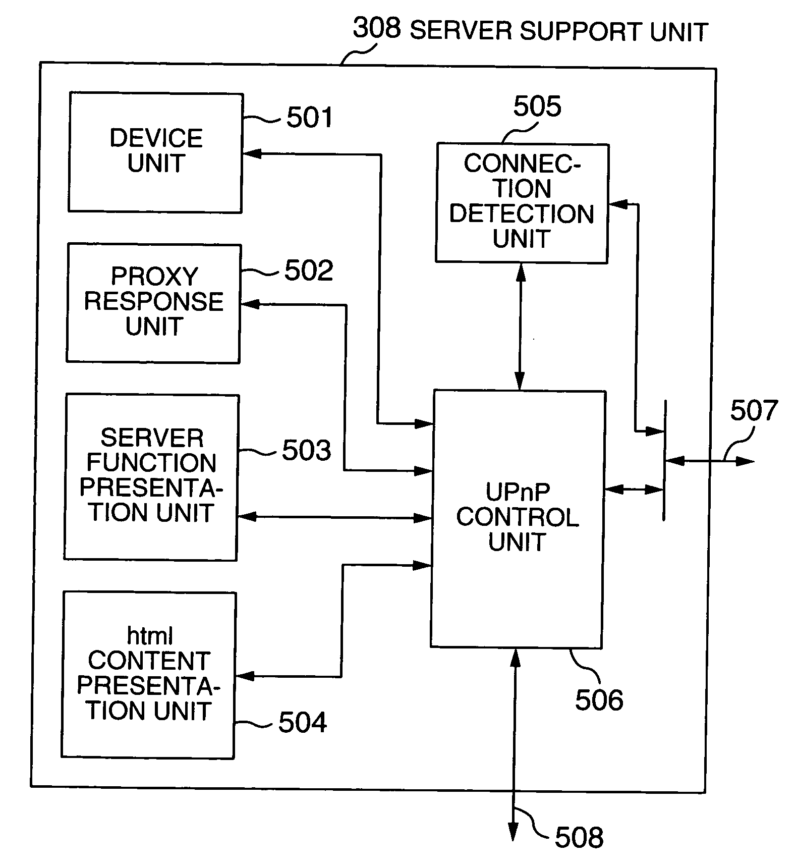
Figure 1 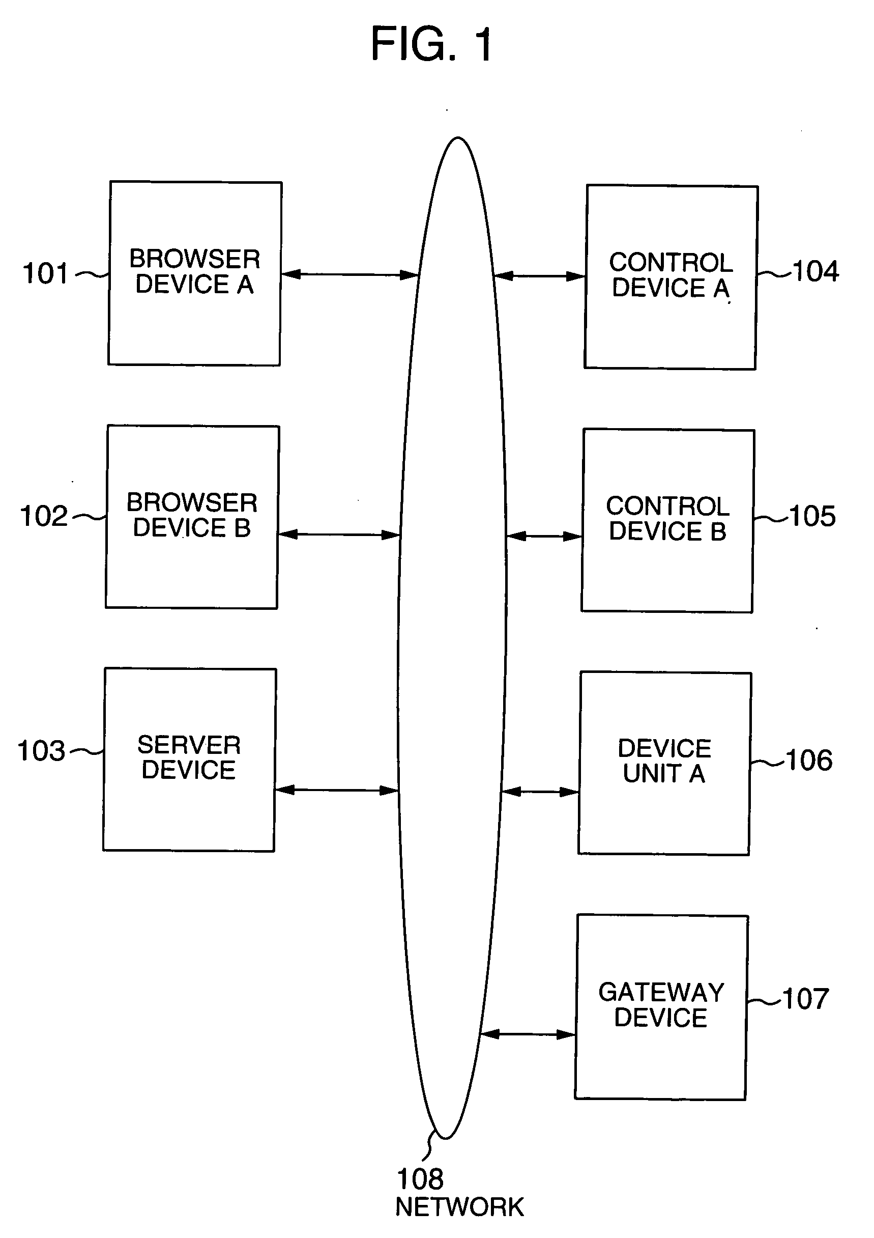
Figure 2 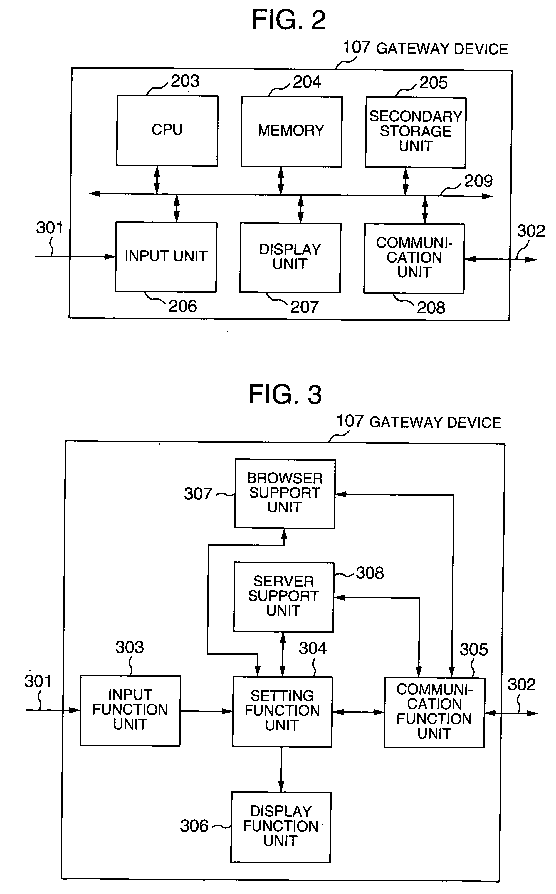
Figure 3
Abstract
Description
[0001] The present application claims priority from Japanese application JP2004-079454 filed on Mar. 19, 2004, the content of which is hereby incorporated by reference into this application. BACKGROUND OF THE INVENTION
[0002] The present invention relates to a method for controlling an information processing apparatus such as a home electric appliance and a personal computer (PC) connected to a network and in particular, to an information processing apparatus and a control method for realizing control between information processing apparatuses of different control methods in a network configuration having a plurality of information processing apparatuses of different control methods.
[0003] Conventionally, as the technique relating to a control method of an information processing apparatus in a network system having a plurality of control methods, for example, JP-A-2003-46535 discloses a network system having two networks connected to apparatuses of two connection methods: the home ...
Examples
embodiment 1
[0032] Description will now be directed to a first embodiment of the present invention with reference to FIG. 1 to FIG. 11. FIG. 1 shows a network configuration of an information processing apparatus (hereinafter, referred to as a gateway device) of the present invention. FIG. 2 shows a system configuration showing hardware configuration of the gateway device connected to the network of FIG. 1. FIG. 3 is a system block diagram showing the functional configuration of the gateway device. FIG. 4 is a block diagram showing the functional configuration of browser support unit of the gateway device. FIG. 5 is a block diagram showing the functional configuration of the server support unit of the gateway device. FIG. 6 to FIG. 8 are processing flowcharts for explaining operation of the browser support unit. FIGS. 9 to 11 are processing flowcharts for explaining operation of the server support unit.
[0033] In FIG. 1, reference numerals 101 and 102 represent browser devices such as PC and hom...
embodiment 2
[0070] Hereinafter, explanation will be given on a second embodiment of the present invention with reference to FIG. 12. This embodiment relates to a network system including a plurality of gateway devices which perform linked operation.
[0071] In FIG. 12, the reference numeral 303 denotes an input unit equivalent to the input unit 303 of FIG. 3; 306 denotes a display function unit equivalent to the display function unit 306 of FIG. 3; and 307 denotes a browser support unit equivalent to the browser support unit 307 of FIG. 3. The reference numeral 1201 denotes a distribution control function unit for controlling the linked operation of the server support unit of the plurality of gateway devices; 1202 denotes a server support unit compatible of the plurality of gateway devices of the server support function using the distribution control function unit 1201; 1203 denotes a setting function unit equivalent to the setting function unit 304 of FIG. 3; and 1204 denotes a communication fu...