
Thermal control covers
Patent Information
- Authority / Receiving Office
- US · United States
- Current Assignee / Owner
- Publication Date
- 2005-12-29
Smart Images
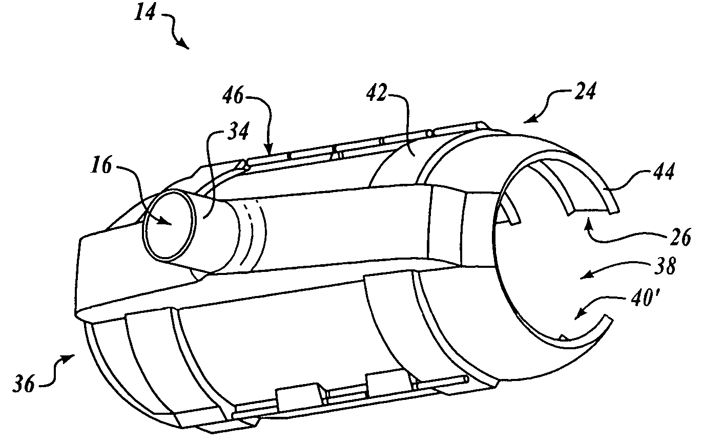
Figure 1 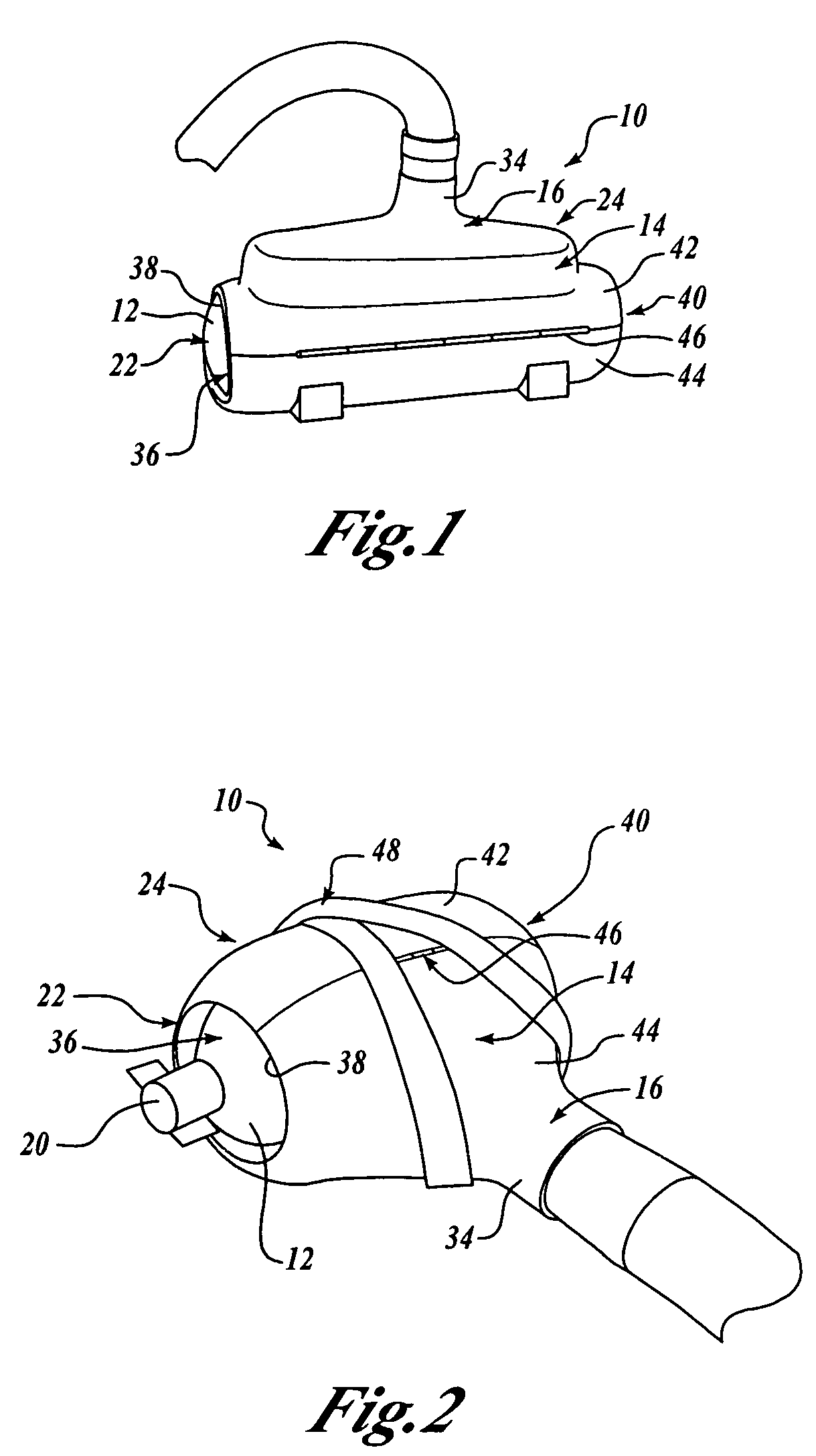
Figure 2 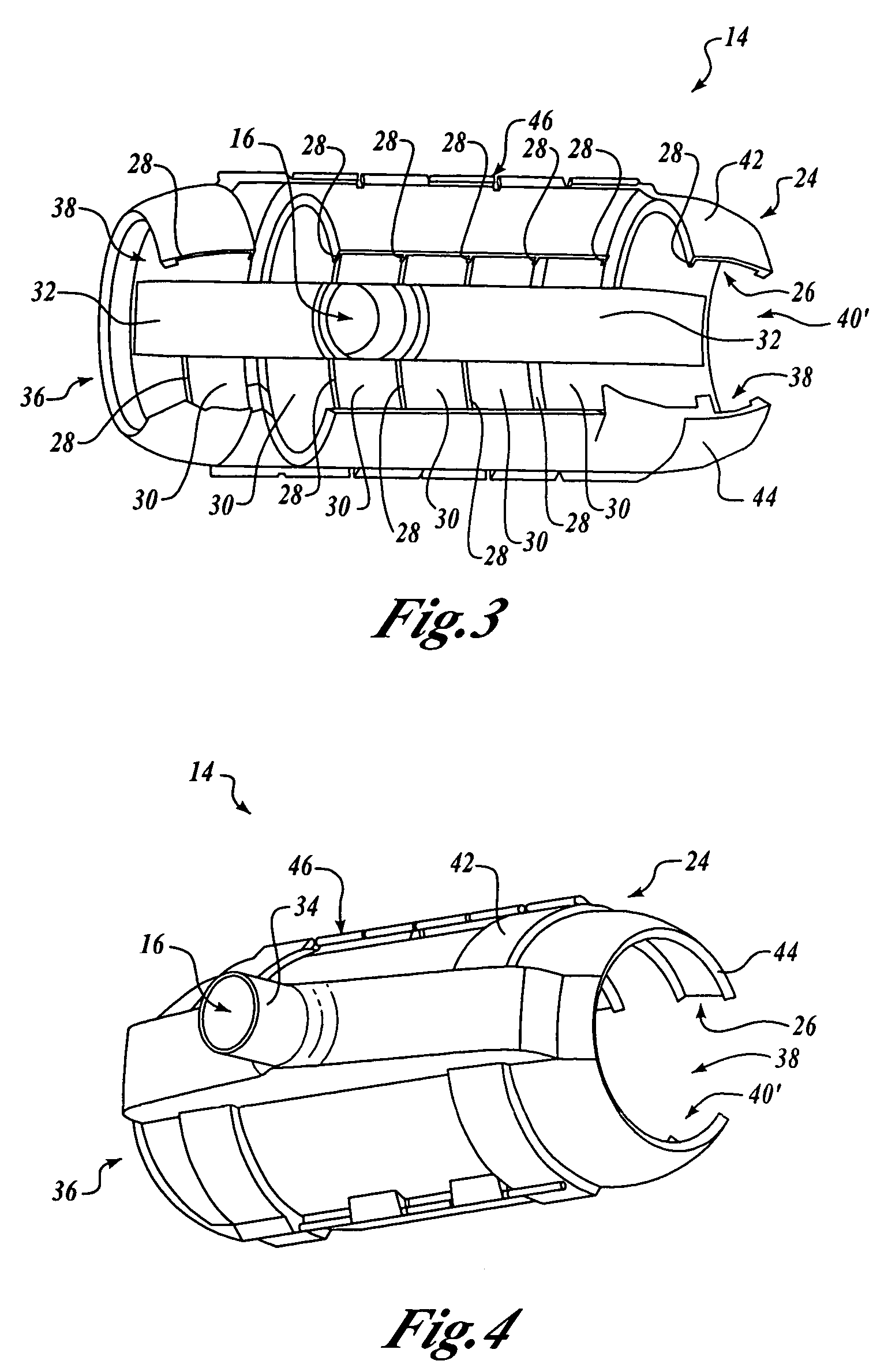
Figure 3
Abstract
Description
FIELD OF THE INVENTION
[0001] This invention relates generally to environmental testing and, more specifically, to pressure testing. BACKGROUND OF THE INVENTION
[0002] Acceptance testing of production items often includes environmental testing, such as pressure testing. For example, a pressure vessel or other production item may be pressurized to verify integrity.
[0003] Typical current pressure test processes utilize dry nitrogen (N2) gas to pressurize a unit under test. N2 gas is used instead of water in order to maintain internal cleanliness of the unit under test (UUT).
[0004] As is known, in a closed gaseous system when pressure increases, temperature also increases. As a result, during a pressurization cycle of pressure testing the N2 gas may heat up to temperatures that exceed engineering design temperature limits of the UUT. As is also known, in a closed gaseous system conversely when pressure decreases, temperature also decreases. As a result, during a depressurization cycl...
Examples
Embodiment Construction
[0019] By way of overview, embodiments of the present invention provide an apparatus and method for mitigating temperature changes of an object. Advantageously, embodiments of the present invention can enable pressure testing to be performed without temperature excursions beyond engineering design temperature limits and without insertion of excessive delays. This can result in reductions in touch labor and can help minimize bottlenecks in production lines. Also, according to another embodiment of the present invention, an apparatus for mitigating temperature changes of an object can be fabricated quickly and inexpensively using rapid prototyping manufacturing techniques.
[0020] Referring now to FIGS. 1 and 2, a cover 10 is provided for mitigating temperature changes of an object 12. The cover 10 includes a cover body 14 configured to receive therein the object 12. A plurality of heat transfer channels (not shown in FIG. 1) are defined in an interior of the cover body 14, and the cha...