
OFDM signal transmission method, and OFDM signal transmitter/receiver
a transmission method and signal technology, applied in multiplex communication, orthogonal multiplex, baseband system details, etc., can solve the problems of reducing the accuracy of phase error detection, bare a problem in an environment where any higher-level noise, and unable to compensate for the amplitude error caused, etc., to achieve the effect of lowering the error ra
Patent Information
- Authority / Receiving Office
- US · United States
- Patent Type
- Applications(United States)
- Current Assignee / Owner
- Publication Date
- 2006-05-18
- Estimated Expiration
- Not applicable · inactive patent
Smart Images
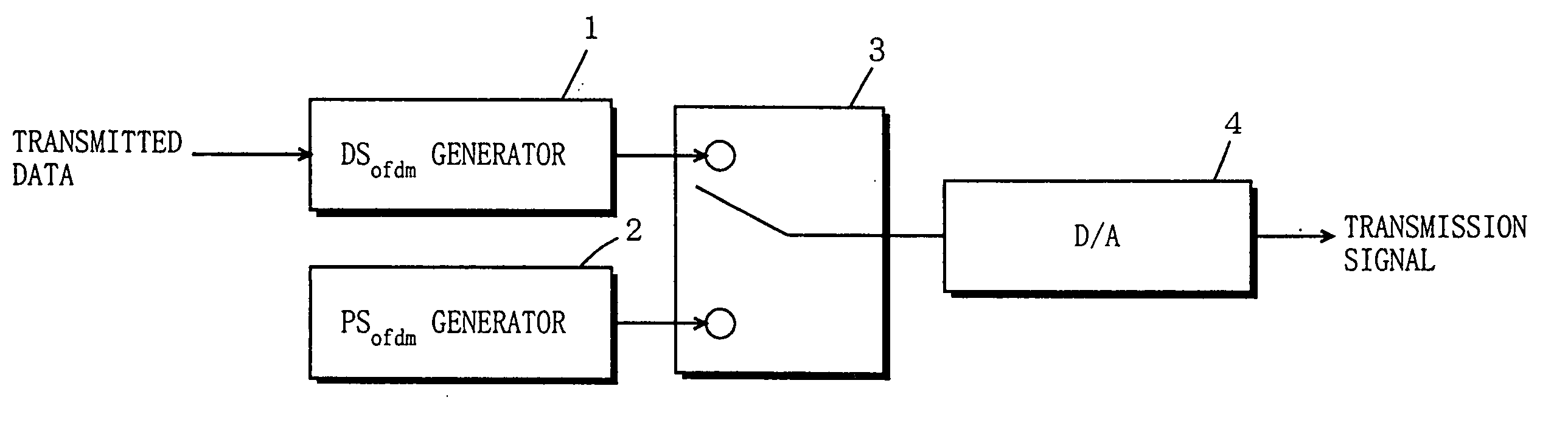
Figure 1 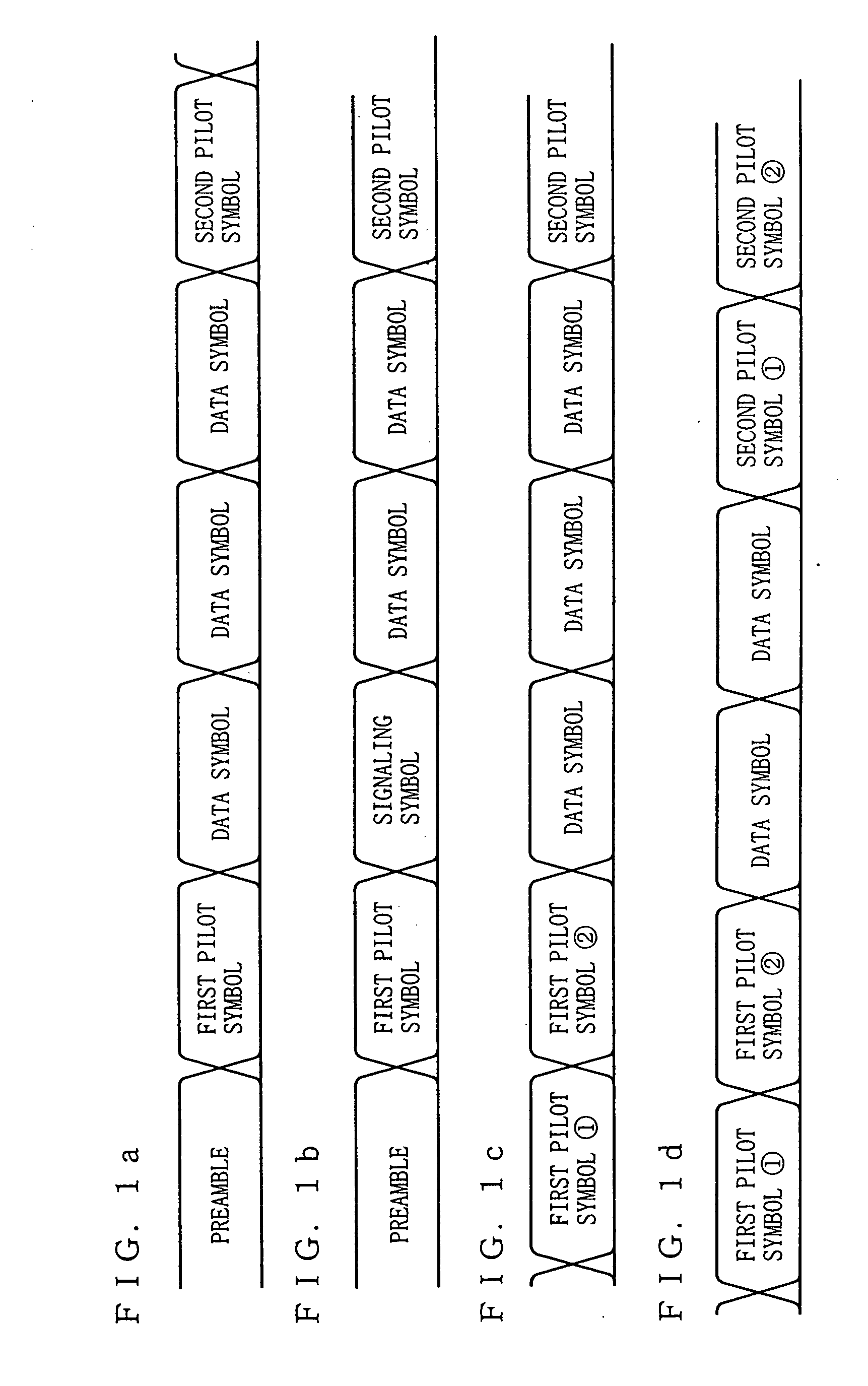
Figure 2 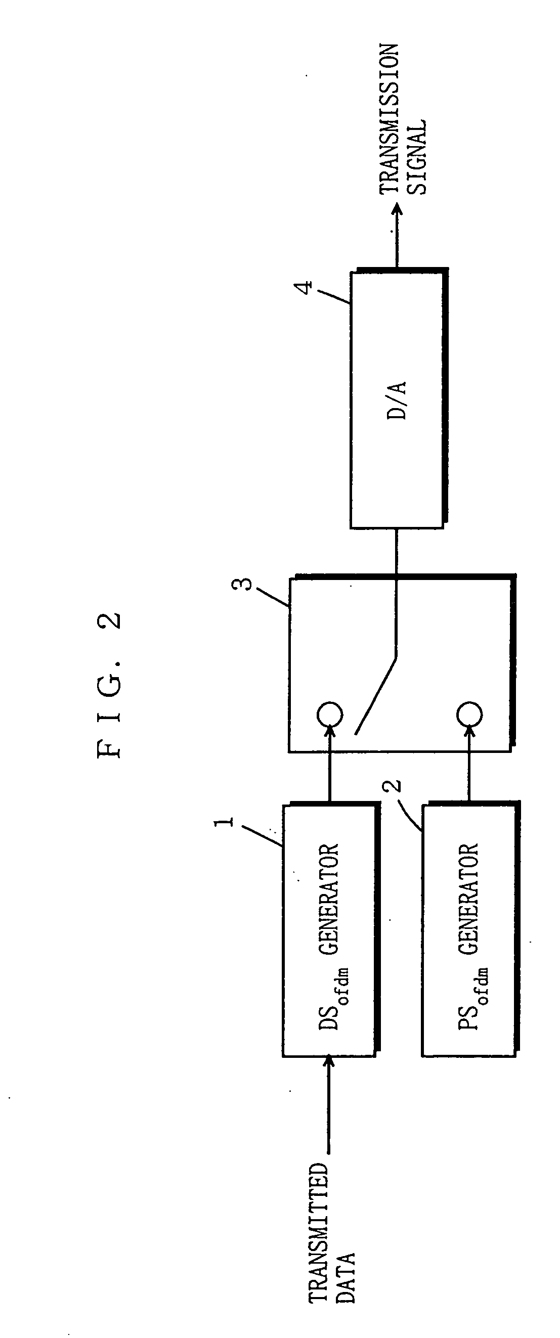
Figure 3
Abstract
Description
[0001] This application is a divisional application of Ser. No. 09 / 627,781, filed Jul. 28, 2000.BACKGROUND OF THE INVENTION
[0002] 1. Field of the Invention
[0003] The present invention relates to an OFDM (Orthogonal Frequency Division Multiplexing) transmission method, and more specifically to a scheme for transmitting data via a wired or wireless transmission path by using an OFDM signal, and a transmitter / receiver therefor.
[0004] 2. Description of the Background Art
[0005] In an OFDM signal transmission scheme, a demodulation characteristic deteriorates due to any distortion observed in a transmission path, out-of-synchronization after passage of time, frequency drift between a transmission side and a reception side, amplitude and phase errors resulted from phase noise in a local oscillator provided in a receiver, and the like. Such error factors provoking the demodulation characteristic to deteriorate are hereinafter referred to as frequency response variation.
[0006] In the OF...
Examples
first embodiment
[0123] First, described below is a transmission scheme according to a first embodiment of the present invention. FIGS. 1a to 1d are diagrams each showing the structure of an OFDM signal to be transmitted under the transmission scheme of the first embodiment. As shown in FIG. 1, a pilot symbol is accompanied by a plurality of data symbols. The pilot symbol has a frequency component predetermined in amplitude and phase. After the data symbols, another pilot symbol follows. As such, the OFDM signal under the transmission scheme of the first embodiment takes such structure that the pilot symbol is inserted before and after one or more data symbols. Herein, the number of pilot symbols to be inserted is not limited, but in a row if plurally provided.
[0124] The OFDM signal includes subcarriers, and the symbol length remains the same regardless of the number of subcarriers included therein. Accordingly, the subcarriers may be predetermined in amplitude and phase either wholly or partially....
second embodiment
[0167] A transmission scheme according to a second embodiment of the present invention is quite similar to the one described in the first embodiment. Further, a transmitter of the second embodiment is structurally identical to the one in the first embodiment, and is not described twice. A receiver of the second embodiment, however, is partially different in structure from the one in the first embodiment, and thus a description is made focusing on the difference.
[0168]FIG. 10 is a schematic view showing the structure of the receiver of the second embodiment. The receiver is provided with the Fourier transformer 5, a phase compensator 26 for compensating for a phase of a signal provided by the Fourier transformer 5, and the demodulator 7 for demodulating a signal outputted from the phase compensator 26. As such, the receiver of the second embodiment includes the phase compensator 26 as an alternative to the TPFR compensator 6 in the receiver in FIG. 4.
[0169] The phase compensator 26...