
Apparatus and method for the position checking of a mechanical part
a technology for mechanical parts and apparatuses, applied in the direction of counting objects on conveyors, manufacturing tools, instruments, etc., can solve the problems of particularly expensive embodiments according to the former japanese patent application, and achieve the effects of accurate, reliable and inexpensive, and avoiding damag
Patent Information
- Authority / Receiving Office
- US · United States
- Current Assignee / Owner
- Publication Date
- 2006-07-13
- Estimated Expiration
- Not applicable · inactive patent
Smart Images
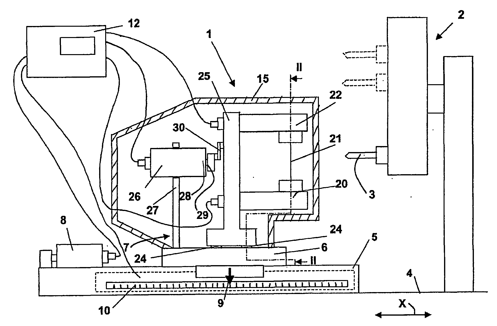
Figure 1 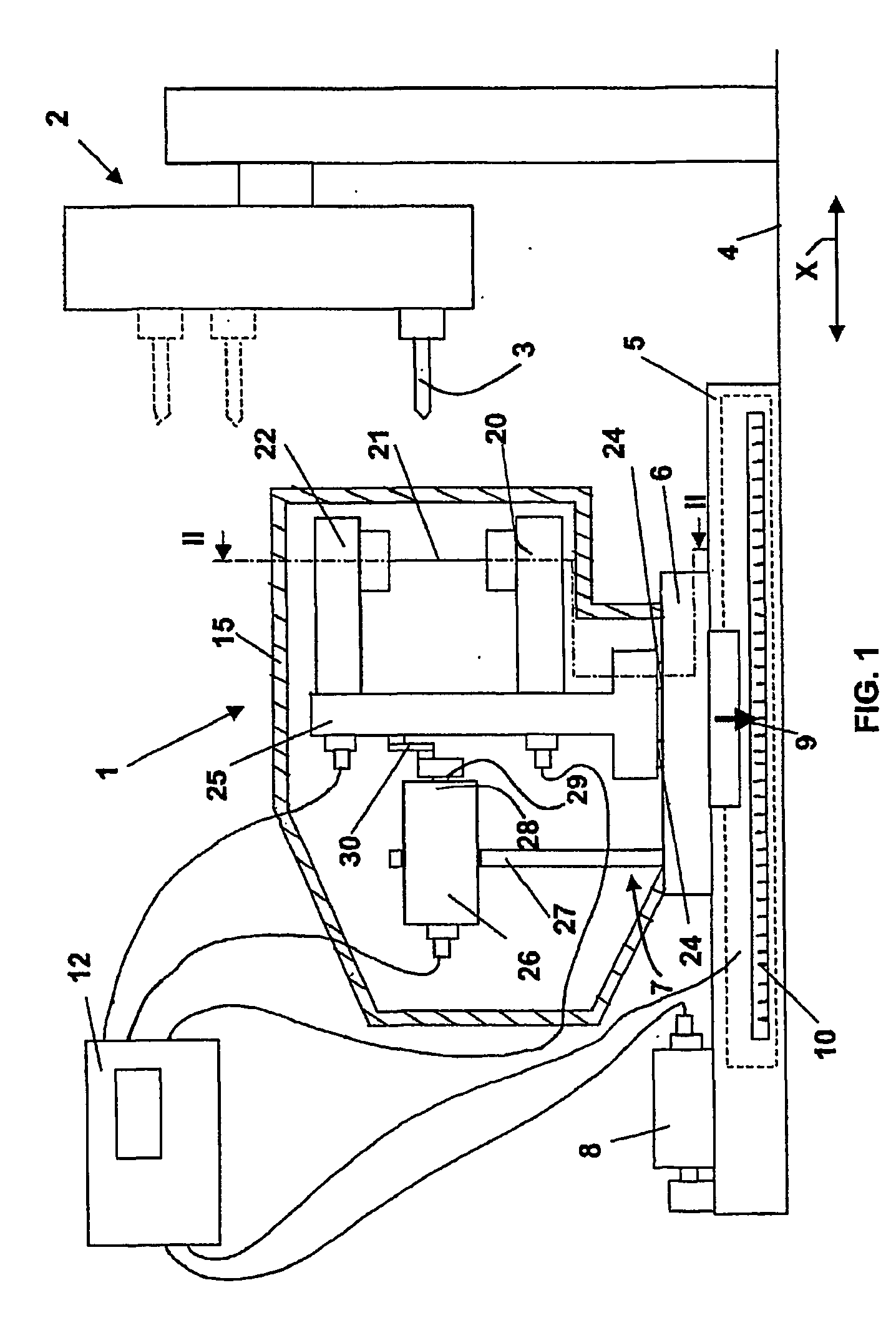
Figure 2 
Figure 3
Abstract
Description
TECHNICAL FIELD
[0001] The invention relates to an apparatus for checking the position of a mechanical part, more particularly a free end of an elongate tool, including a frame, stationary with respect to the mechanical part to be checked, a base carrying a mechanical support, the base and the frame being mutually movable along a longitudinal feed direction, an emitter for generating a light beam along a trajectory transversal with respect to the longitudinal feed direction, and a sensor, arranged along the trajectory of the light beam, the emitter and the sensor being coupled to the mechanical support in mutually defined positions, the sensor being adapted for providing signals indicative of the reception of the light beam, a transducer device for checking the mutual position between the base and the frame, and a processing, display and control unit, connected to the sensor and to the transducer device for processing the signals of the sensor and for identifying the mutual position...
Examples
Embodiment Construction
[0017]FIG. 1 illustrates a checking apparatus 1 represented in course of checking a mechanical part, in particular an elongate tool 3 coupled to a storage magazine 2 of a machine tool, for example a machining center, per se known and herein not illustrated.
[0018] A common bed 4 supports the storage magazine 2 and the apparatus 1. More specifically, a frame of the apparatus, shown in simplified form in FIG. 1 and identified by reference number 5, is rigidly coupled to bed 4 and carries a slide 6—movable with respect to frame 5 and consequently with respect to tool 3, along a longitudinal feed direction X—that forms a base for a hereinafter disclosed optoelectronic checking system 7.
[0019] A displacement system for controlling and checking the mutual position between base 6 and frame 5 includes, for example, a motor 8 that activates the displacements of the slide 6, with respect to the frame 5, and a position checking transducer device, for example a linear transducer. The linear tr...