
DNA amplification device
a dna amplification and amplification technology, applied in the field of dna amplification devices, can solve the problems of reducing reducing process efficiency, and reducing process efficiency. the effect of reducing the duration and improving the process efficiency and power saving properties
Patent Information
- Authority / Receiving Office
- US · United States
- Patent Type
- Applications(United States)
- Current Assignee / Owner
- Publication Date
- 2006-07-27
- Estimated Expiration
- Not applicable · inactive patent
Smart Images
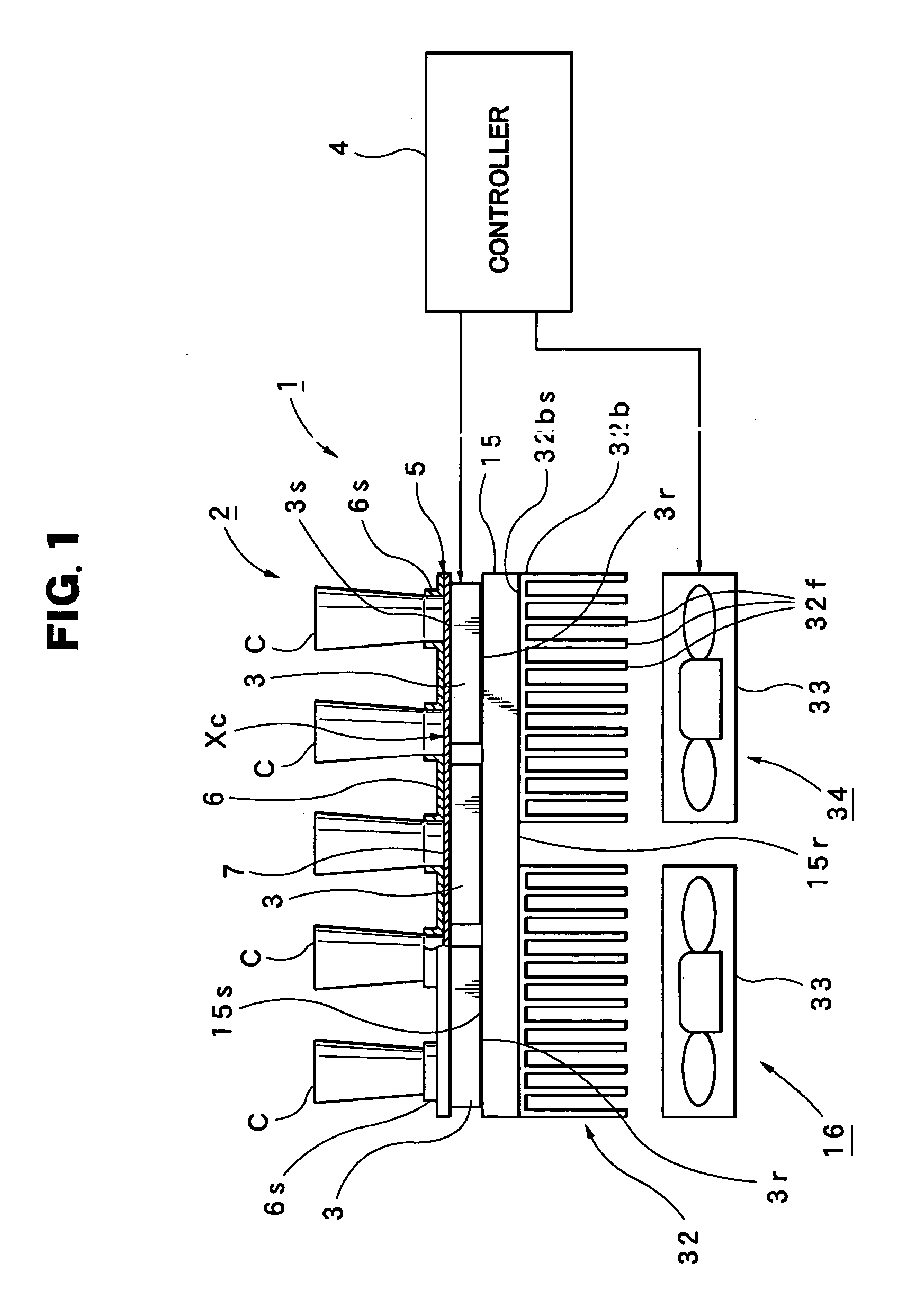
Figure 1 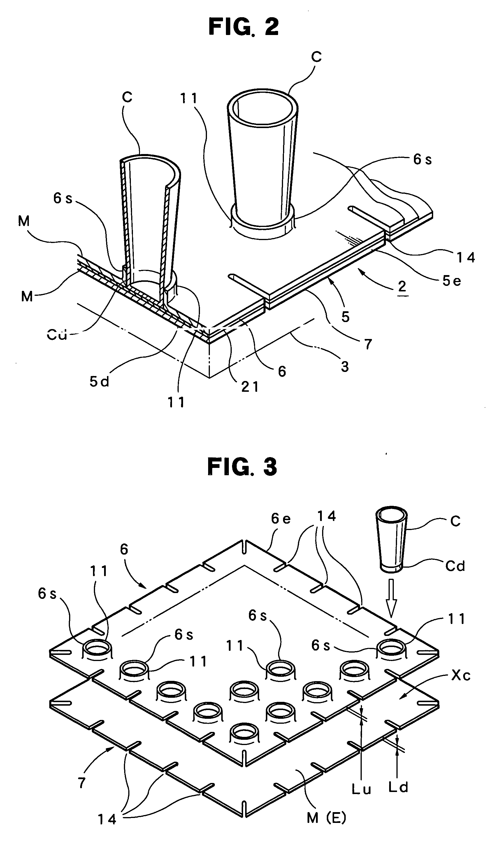
Figure 2 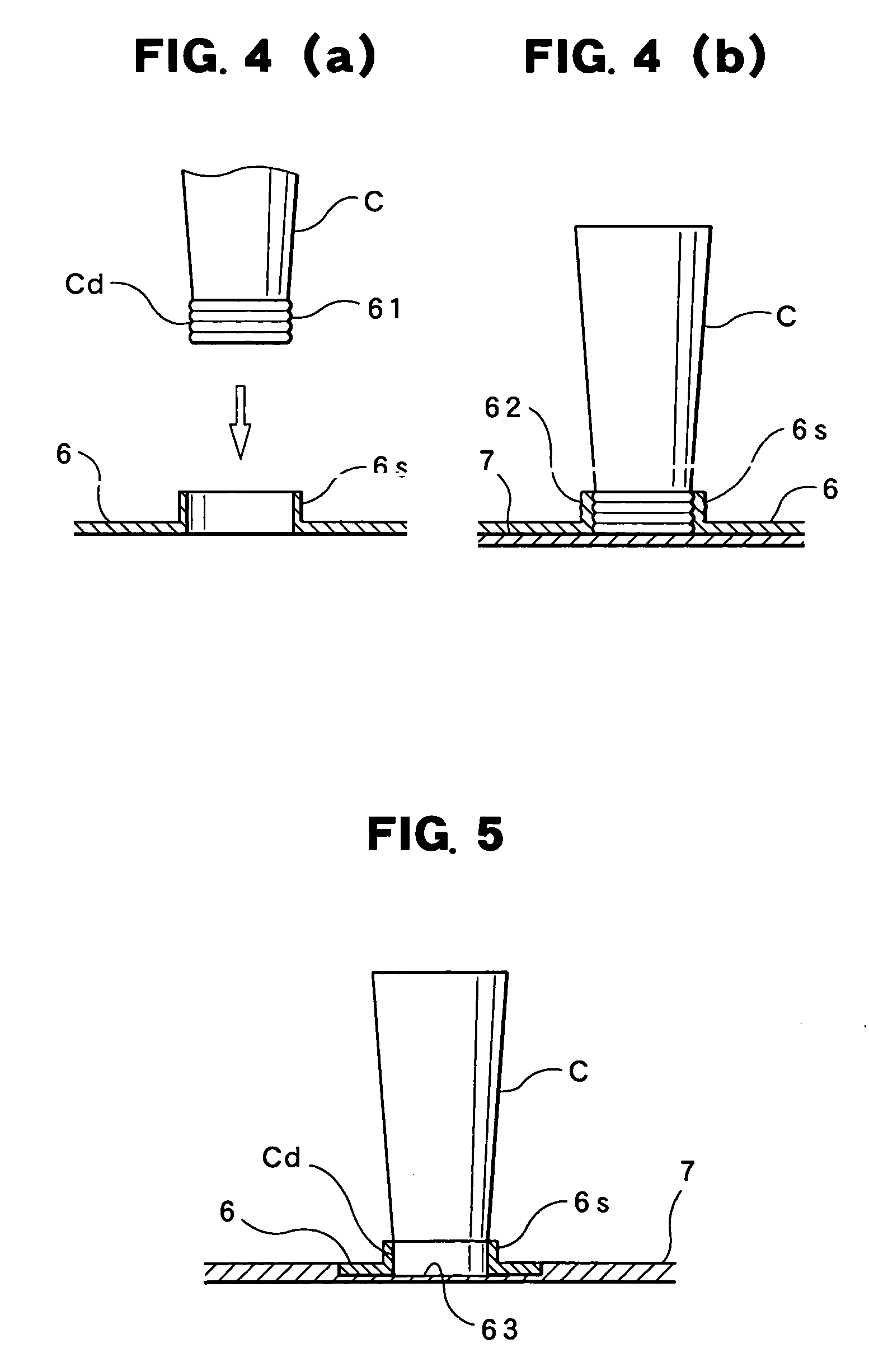
Figure 3
Abstract
Description
BACKGROUND OF THE INVENTION
[0001] 1. Field of the Invention
[0002] The present invention relates to a DNA amplification device suitable for use when amplifying DNA (deoxyribonucleic acid).
[0003] 2. Description of the Relevant Art
[0004] In general, the PCR method (polymerase chain reaction method) is known as a method for DNA amplification. The PCR method is a method where primers, an enzyme(s) and deoxyribonucleoside triphosphate, reacted with a DNA sample, are added to the DNA sample, whereupon the reaction solution is heated (or cooled down) by a heat cycle changed according to a pre-determined temperature pattern, and concurrently, where the sequential repetition of the heat cycle results in the amplification of the DNA.
[0005] Another DNA amplification device for realizing the PCR method is also known, for example, in the publication of Japanese Laid-Open Patent Application No. 2003-174863, which discloses a DNA amplification device equipped with a heating & cooling means est...
Examples
Embodiment Construction
[0037] Preferred embodiments relating to the present invention are described hereafter, with reference to the drawings. The present invention is not limited to the attached drawings which are provided for easily understanding the present invention. Further, detailed descriptions of the well-known portions are omitted in order to avoid ambiguity.
[0038] First, the construction of a DNA amplification device 1 relating to the present invention is described hereafter with reference to FIG. 1 through FIG. 3.
[0039] In FIG. 1, the symbol 3 . . . indicates one, two or more thermo-modules. Each thermo-module 3 . . . is the basically the same as the above-mentioned thermo-module 3 shown in FIG. 15. In other words, the thermo-module 3 is constructed with a structure in which multiple peltiert elements d . . . are connected [with each other] and are regarded as the series aggregate P, and this series aggregate P is interposed by a pair of the substrates 51&52. The multiple electrodes e . . . a...