
Boring machine
a boring machine and cutting edge technology, applied in earth drilling and mining, earth drilling tools, pipe/joints/fittings, etc., can solve the problems of cutting edge biting or breaking the cutting edge, cutting force, cutting edge crashing into the workpiece, etc., to achieve the effect of reducing the radius of rotation of the handle, and large torqu
Patent Information
- Authority / Receiving Office
- US · United States
- Patent Type
- Applications(United States)
- Current Assignee / Owner
- Publication Date
- 2006-08-10
- Estimated Expiration
- Not applicable · inactive patent
Smart Images
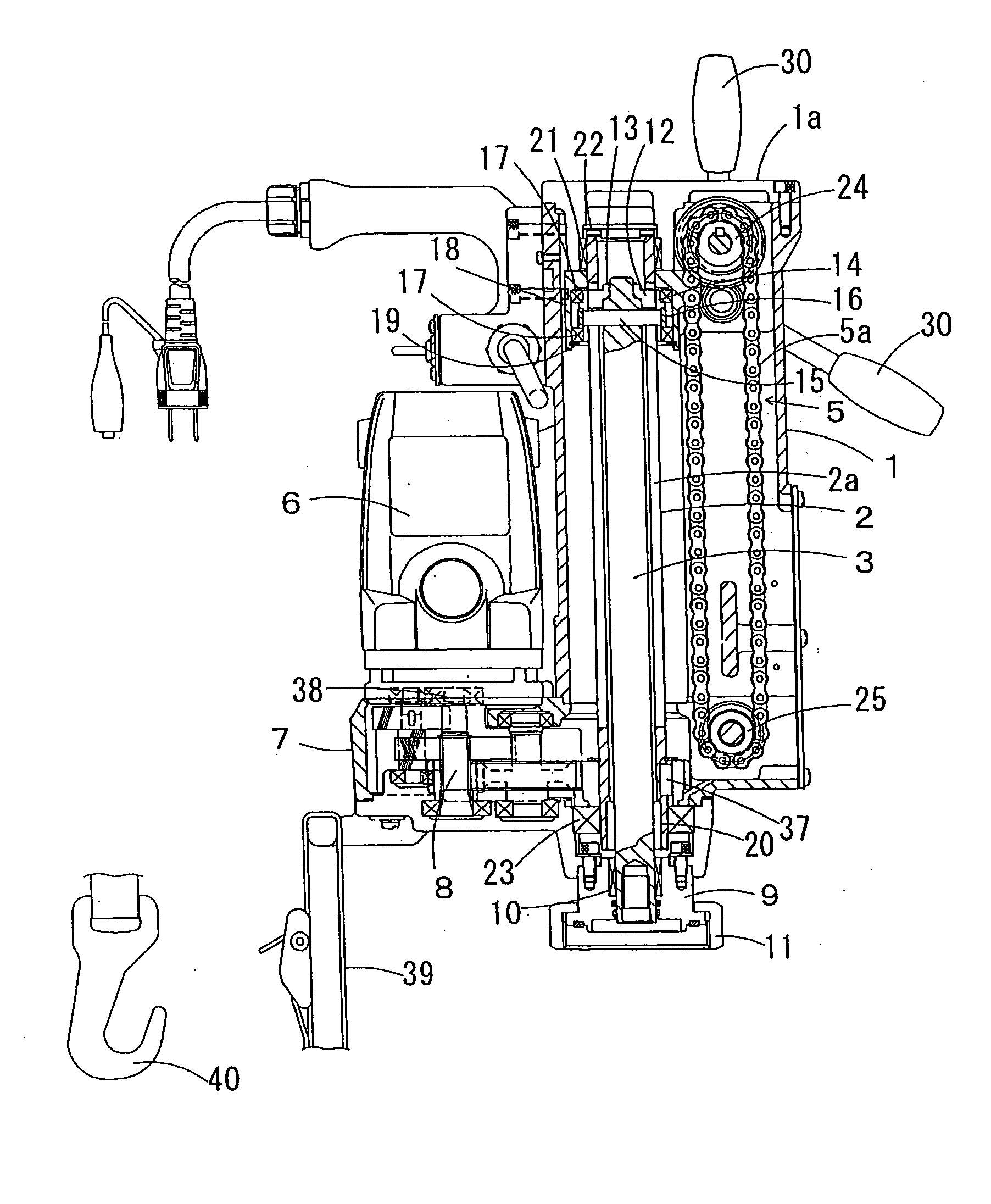
Figure 1 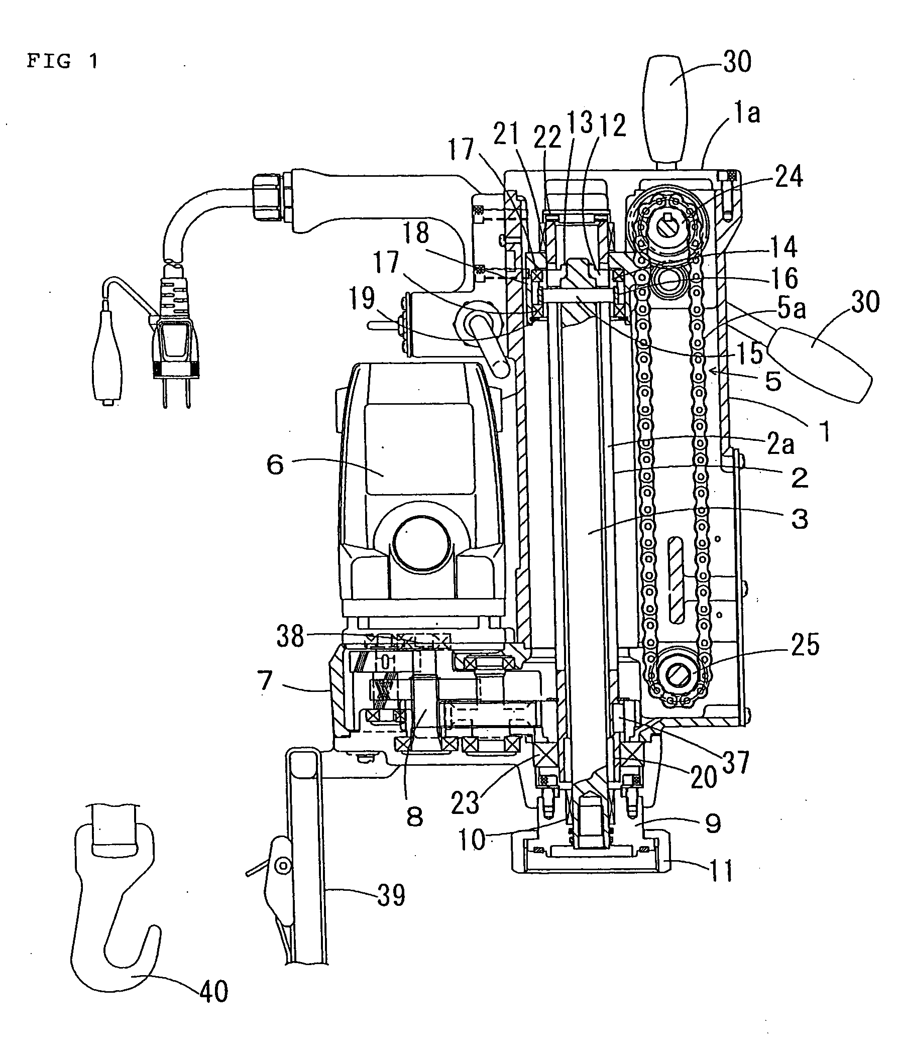
Figure 2 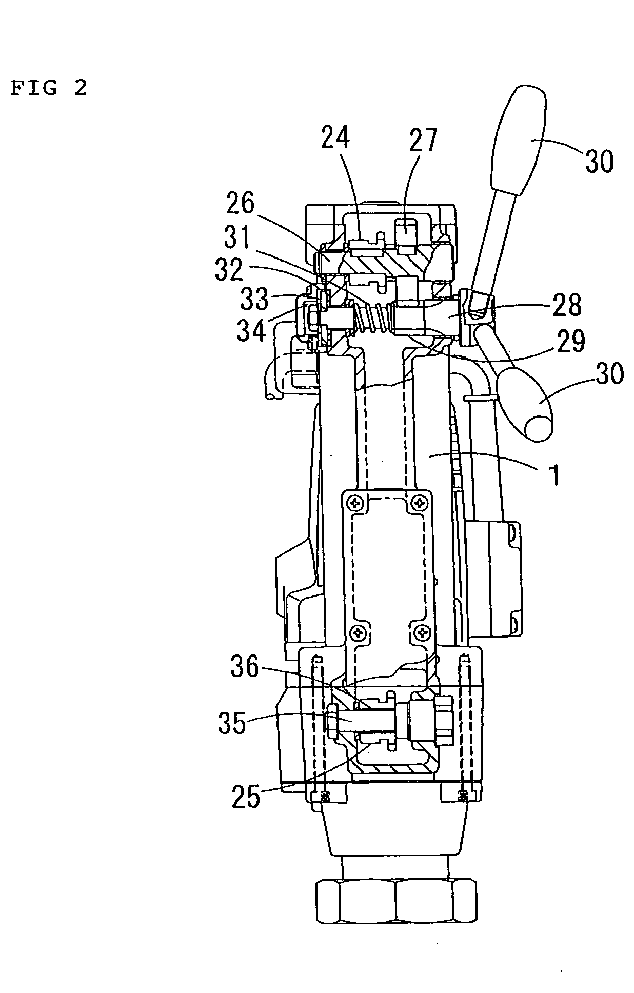
Figure 3
Abstract
Description
BACKGROUND OF THE INVENTION
[0001] 1. Field of the Invention
[0002] The present invention relates to improvements in boring machines for drilling holes for branch line on one of a main line of water pipe and a gas pipe for branch line.
[0003] 2. Description of the Related Art
[0004] In a conventional method of attaching a branch line to one of a water-pipe main line and a gas-pipe main line, a saddle corporation stop is typically fixed onto the main line, and a hole is drilled on the pipe with a boring machine mounted on the saddle corporation stop. A variety of boring machines has been proposed. For example, Japanese Unexamined Patent Application Publication No. 2002-66819 discloses one boring machine. In the disclosed boring machine, a cutting edge feeding mechanism using a chain is employed, and a cutting edge rotated by a motor is raised and lowered by handle operation.
[0005] More in detail, rotation of the motor arranged in the body of the machine is transferred to a pipe spin...
Examples
Embodiment Construction
[0019] Boring machines of the preferred embodiments of the present invention are described below with reference to the drawings. FIG. 1 is a side view of the boring machine of one embodiment of the present invention with a portion thereof of broken away, FIG. 2 is a front view of the boring machine with a portion thereof of broken away, and FIG. 3 is a partial side view of the boring machine attached onto a saddle corporation stop.
[0020] Referring to FIGS. 1 through 3, there are shown a boring machine 1, a pipe spindle 2 rotatably supported within the boring machine 1, and a shaft 3 vertically slidably supported within the pipe spindle 2. A cutting edge 4 for cutting a water pipe is mounted to an end of the shaft 3 with a mounting shaft. A cutting edge feeding mechanism 5, employing a chain, vertically moves the shaft 3 through the pipe spindle 2. A motor 6 rotates the pipe spindle 2 and the shaft 3 via a reduction gear train 8 in a gear box 7. A saddle bracket 9 is fixed on the lo...