
Vehicle Response During Vehicle Acceleration Conditions
a technology for acceleration conditions and vehicles, applied in the direction of electrical control, process and machine control, instruments, etc., can solve the problems of poor driveability, poor driveability, etc., to increase the response delay, reduce clunk, and improve driveability
Patent Information
- Authority / Receiving Office
- US · United States
- Current Assignee / Owner
- Publication Date
- 2007-09-13
Smart Images
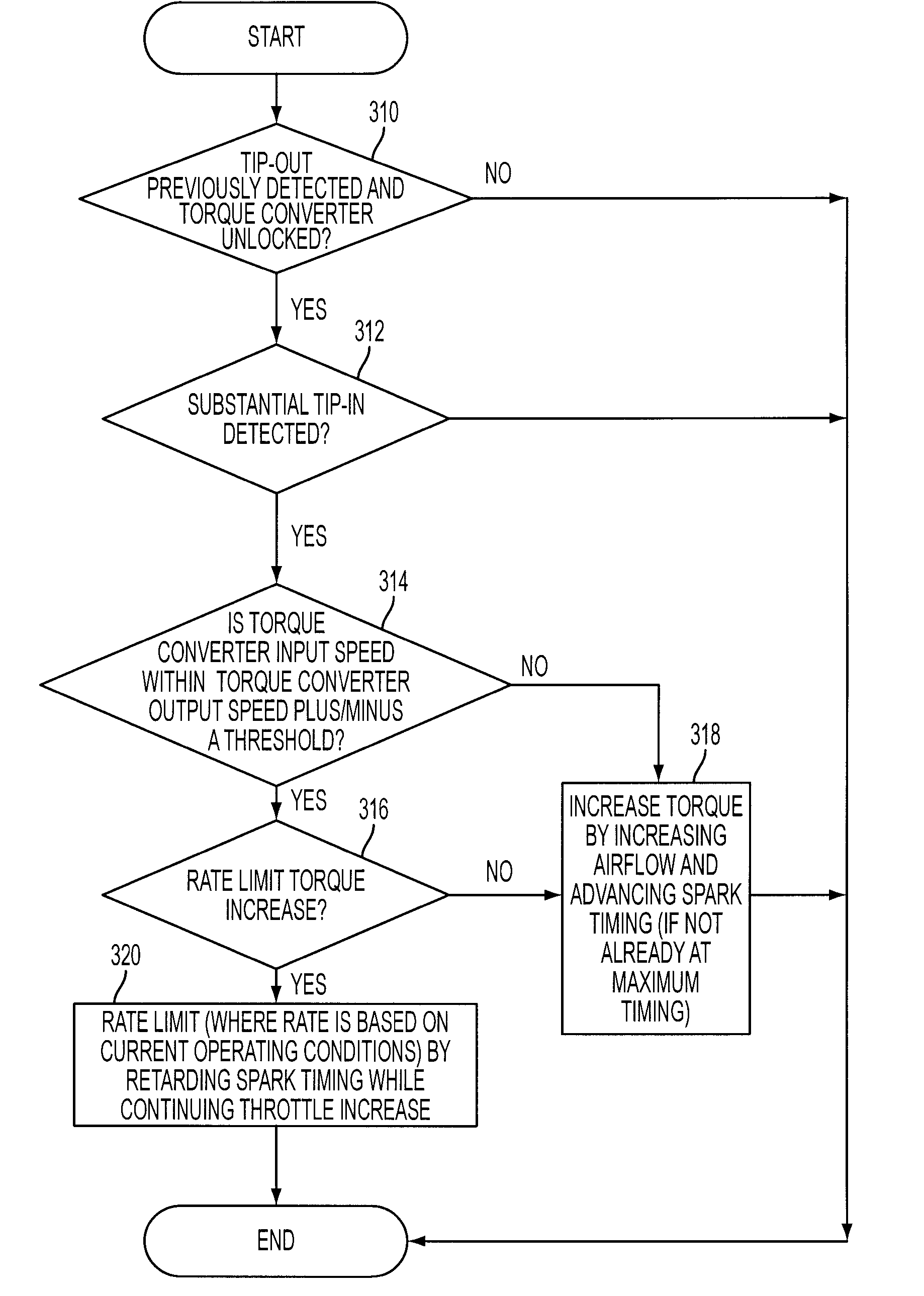
Figure 1 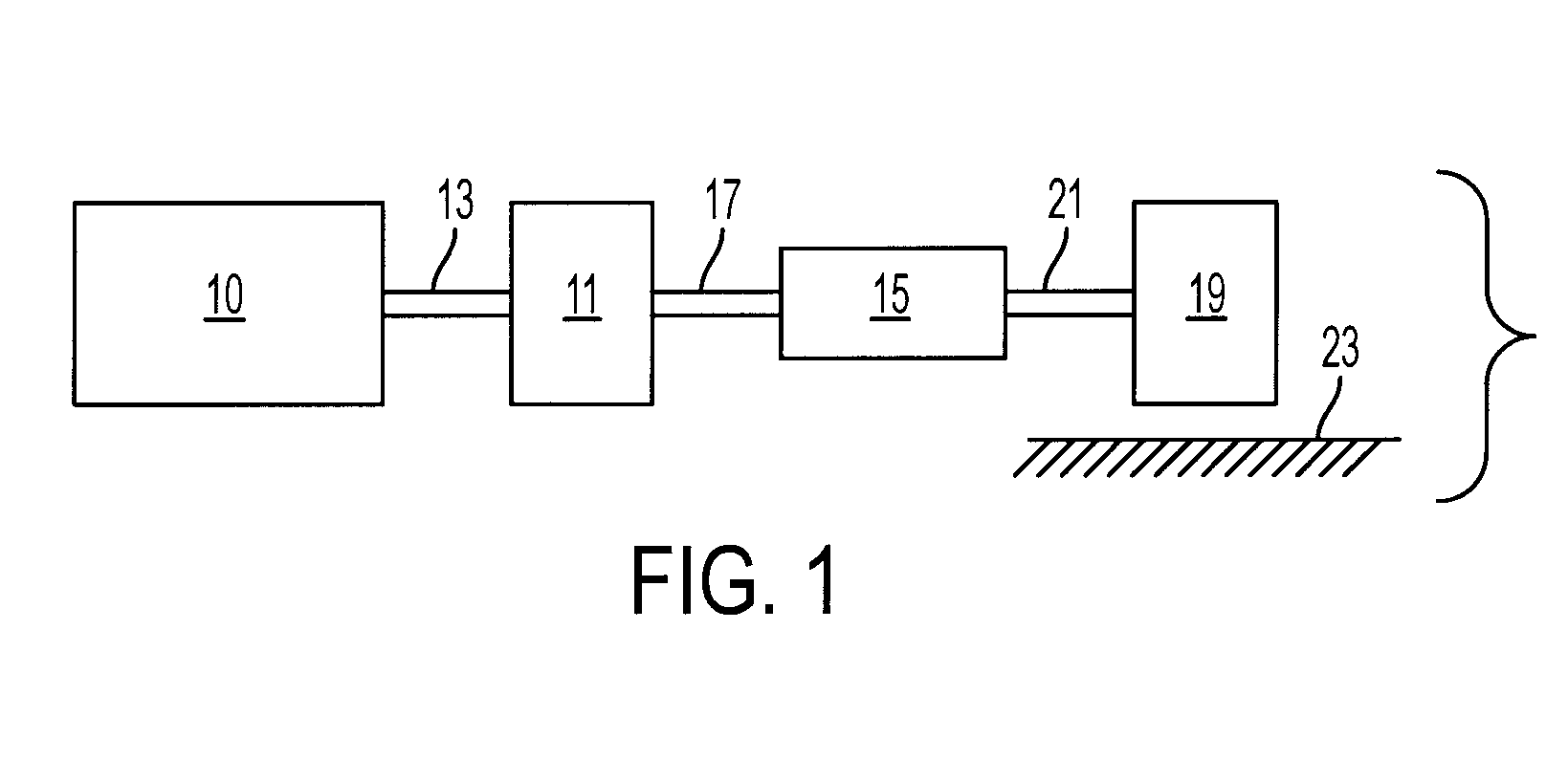
Figure 2 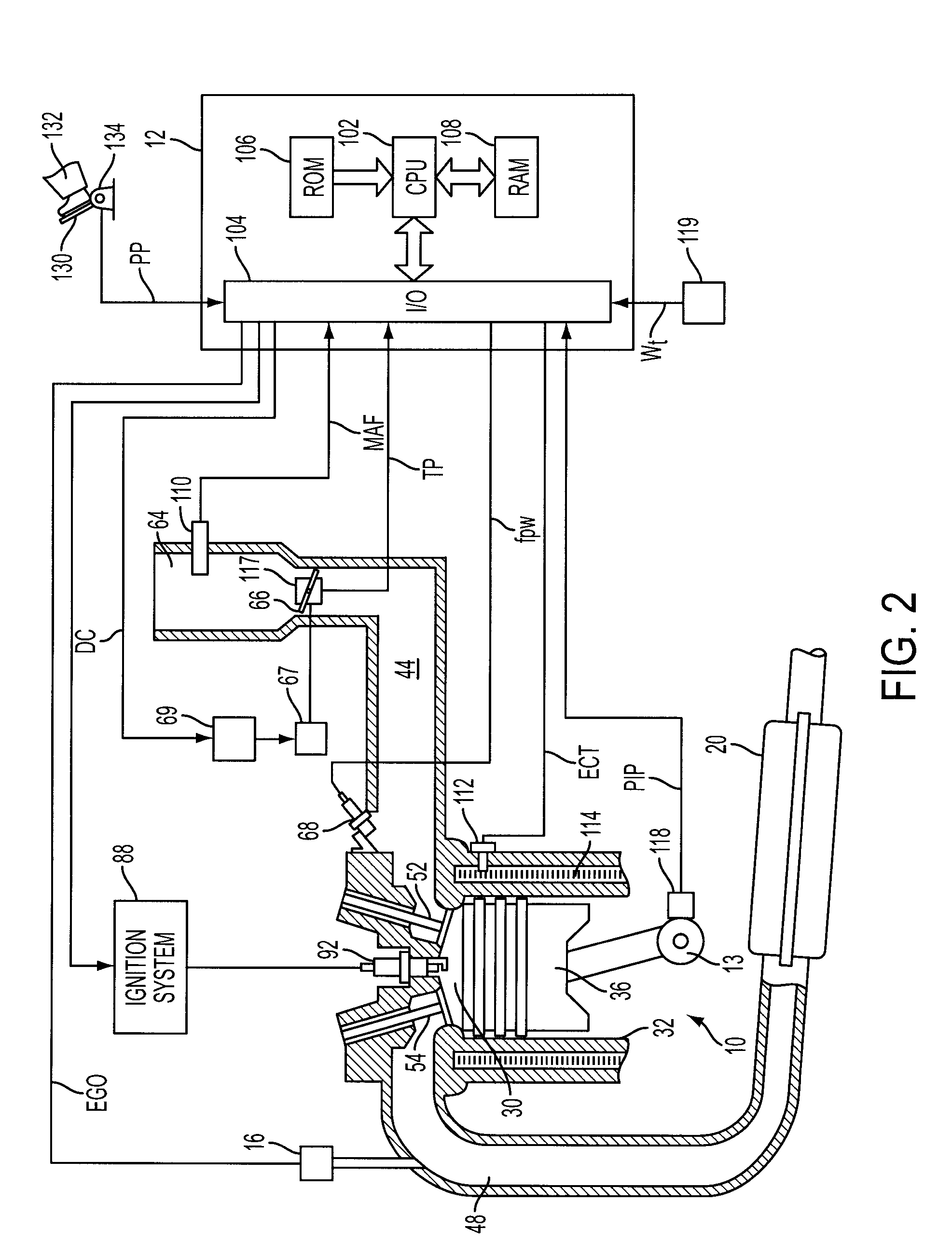
Figure 3
Abstract
Description
[0001] The present application is a continuation-in-part of U.S. patent application Ser. No. 11 / 370,400, filed Mar. 7, 2006, Attorney Docket No. 81136900, entitled “System and Method for Improved Vehicle Response During Vehicle Acceleration Conditions”, the entire contents of which are incorporated herein by reference.FIELD
[0002] The present application relates to engine and vehicle control, and in one example relates to operation during vehicle acceleration following deceleration.BACKGROUND AND SUMMARY
[0003] Internal combustion engines are controlled in many different ways to provide acceptable driving comfort during all operating conditions. Some methods use engine output, or torque, control where the actual engine torque is controlled to a desired engine torque through an output adjusting device, such as with an electronic throttle, ignition timing, or various other devices.
[0004] Under some conditions, there is the potential for poor driveability when the vehicle operator releases a...
Examples
Embodiment Construction
[0017]Referring to FIG. 1, internal combustion engine 10, further described herein with particular reference to FIG. 2, is shown coupled to torque converter 11 via crankshaft 13. Torque converter 11 is also coupled to transmission 15 via turbine shaft 17. Torque converter 11 has a bypass clutch (not shown) which can be engaged, disengaged, or partially engaged. When the clutch is either disengaged or being disengaged, the torque converter is said to be in an unlocked state. Turbine shaft 17 is also known as transmission input shaft.
[0018]In one embodiment, transmission 15 comprises an electronically controlled transmission with a plurality of selectable discrete gear ratios. Transmission 15 may also comprises various other gears, such as, for example, a final drive ratio (not shown). Alternatively, transmission 15 may be a continuously variable transmission (CVT). In still another example, transmission 15 may be a manual transmission, an automated manual transmission, a powershift t...