
Apparatus for the fibre-sorting or fibre-selection of a fibre bundle comprising textile fibres, especially for combing
Patent Information
- Authority / Receiving Office
- US · United States
- Current Assignee / Owner
- Publication Date
- 2009-01-01
- Estimated Expiration
- Not applicable · inactive patent
Smart Images
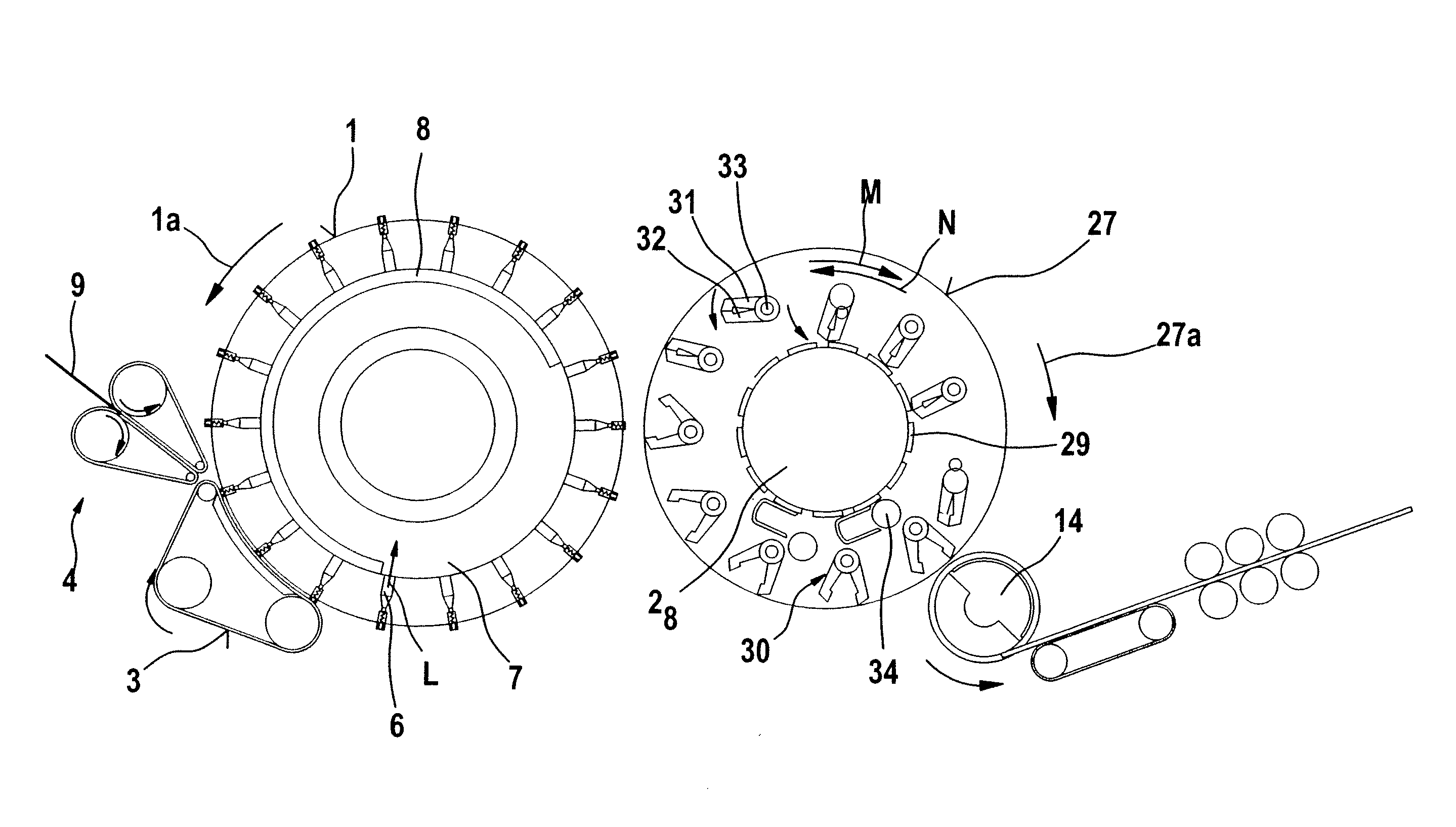
Figure 1 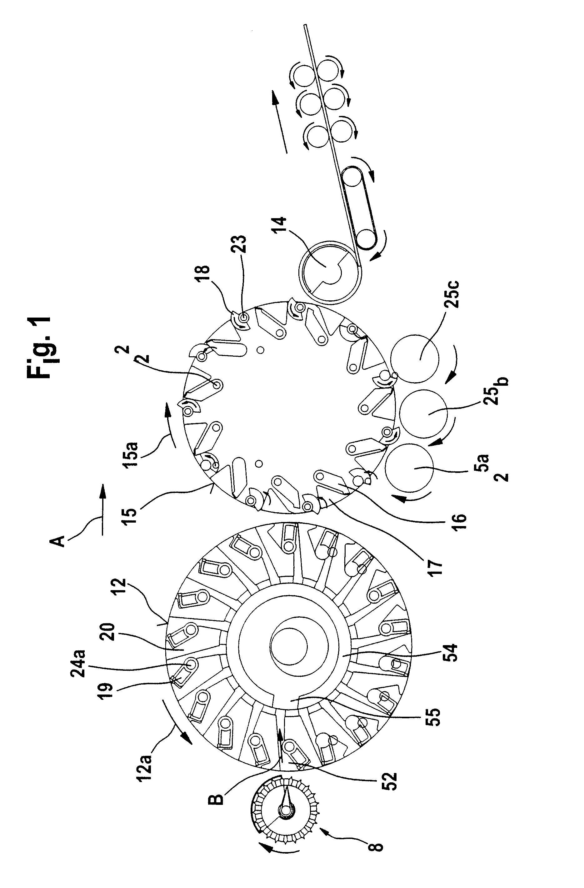
Figure 2 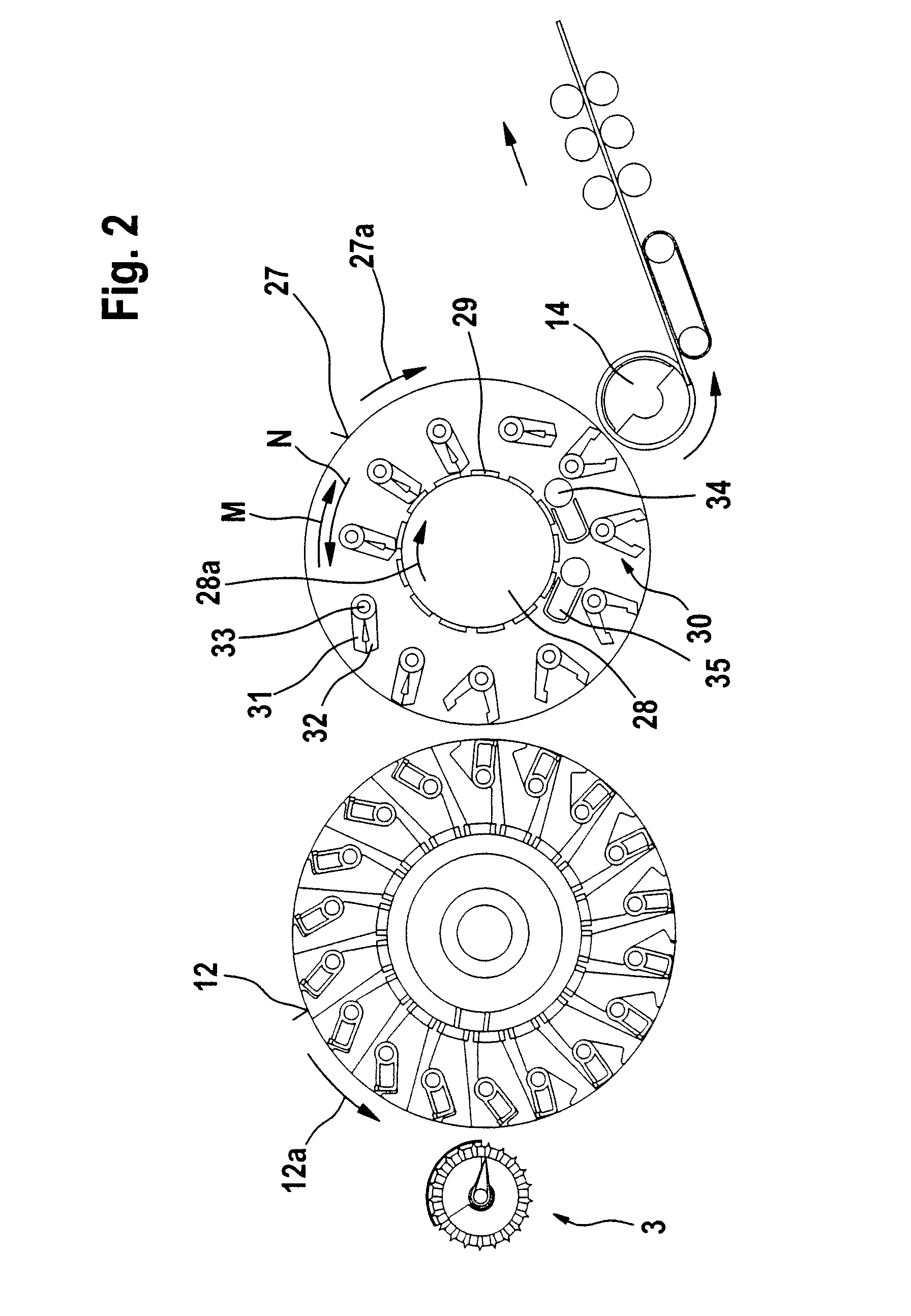
Figure 3
Abstract
Description
CROSS REFERENCE TO RELATED APPLICATIONS
[0001] This application claims priority from German Patent Application No. 10 2007 030 393.0 dated Jun. 29, 2007, German Utility Model No. 20 2007 010 686.6 dated Jun. 29, 2007, and German Patent Application No. 10 2008 004 096.7 dated Jan. 11, 2008, the entire disclosure of each of which is incorporated herein by reference.BACKGROUND OF THE INVENTION
[0002] The invention relates to an apparatus for the fibre-sorting or selection of a fibre bundle comprising textile fibres, especially for combing, which is supplied by means of supply means to a fibre-sorting device, especially to a combing device. It is known in a combing device to provide clamping devices, which clamp the fibre sliver at a distance from its free end, mechanical means being present which generate a combing action from the clamping site to the free end of the fibre sliver in order to loosen and remove non-clamped constituents, such as, for example, short fibres, neps, dust and the ...
Examples
Embodiment Construction
[0027]FIG. 1 shows a rotor combing machine 2 having a supply device 8, a first roller 12 (turning rotor), a second roller 15 (combing rotor), and a take-off device comprising a take-off roller 14. The directions of rotation of the rollers 12 and 15 are shown by curved arrows 12a and 15a, respectively. The rollers 12, 15 and 14 are arranged one after the other. Arrow A denotes the operating direction.
[0028]Referring to FIG. 1, the rotatably mounted first roller 12 is provided in the region of its outer periphery with a plurality of first clamping devices which extend across the width of the roller 12 and each consist of an upper nipper 19 (gripping element) and a lower nipper 20 (counter-element). In its one end region facing the centre point or the pivot axis of the roller 12, each upper nipper 19 is rotatably mounted on a pivot bearing 24a, which is attached to the roller 12. The lower nipper 20 is mounted on the roller 12 so to be fixed. The free end of the upper nipper 19 faces t...