
Electric compressor
a technology of electric compressor and compressor, which is applied in the direction of positive displacement liquid engine, piston pump, liquid fuel engine, etc., can solve the problems of deteriorating performance of electric motor and compressor, insufficient cooling of stators, and inability to cool all the plurality of stators of electric motor equally, so as to prevent the effect of its performance from decreasing
Patent Information
- Authority / Receiving Office
- US · United States
- Current Assignee / Owner
- Publication Date
- 2009-06-25
- Estimated Expiration
- Not applicable · inactive patent
Smart Images
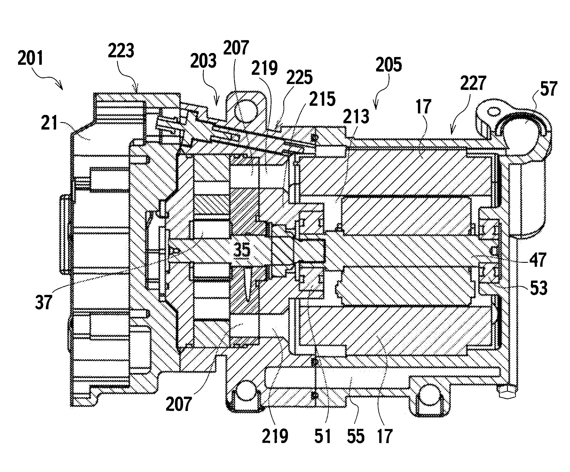
Figure 1 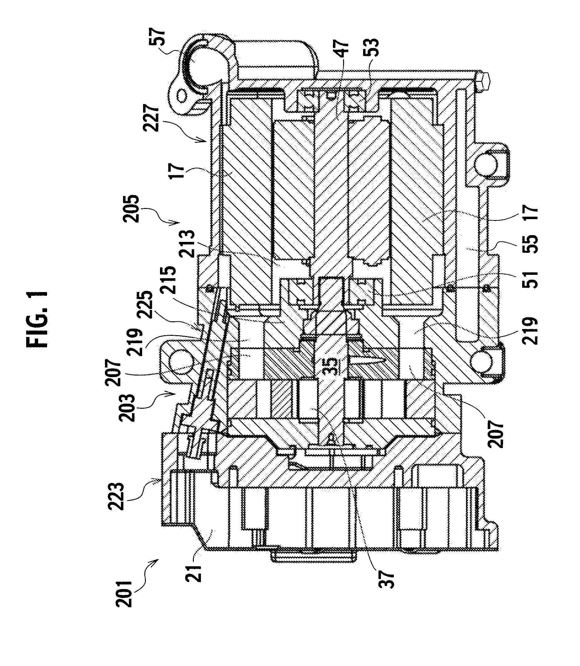
Figure 2 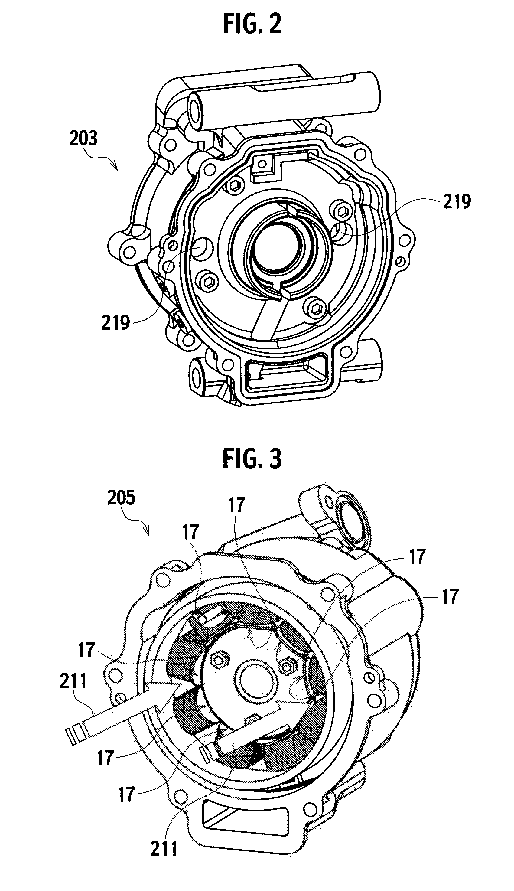
Figure 3
Abstract
Description
BACKGROUND OF THE INVENTION
[0001] 1. Field of the invention
[0002] The present invention relates to an electric compressor.
[0003] 2. Description of the Related Art
[0004] Technologies concerning an electric compressor as an electric gas compressor have been disclosed in Japanese Patent Application Laid-Open No. 2005-344657 (Patent Document 1).
[0005] This electric gas compressor (electric compressor) is used for a cooling system for a vehicle air conditioning system, and includes a compressor configured to compress a refrigerant, and an electric motor configured to drive the compressor. In general, electric compressors are each designed to cool the stators of the electric motor by causing a refrigerant compressed by and delivered from the compressor to flow to the stators.
[0006] The electric compressor in the related art includes a partition wall separating an accommodation chamber accommodating the electric motor and another accommodation chamber accommodating the compressor. The partition ...
Examples
embodiment 1
[0049]Descriptions will be provided for an electric compressor 201 according to Embodiment 1 of the present invention by referring to FIGS. 1 to 3.
[0050]The electric compressor 201 is used in a cooling system for a vehicle air conditioner. Refrigerant (coolant) gas is adiabatically compressed by the electric compressor 201, and becomes high in temperature and pressure. Afterward, this refrigerant is liquefied by a condenser. Subsequently, the refrigerant thus liquefied is pressed and expanded by an expansion valve. After that, through heat exchange by an evaporator, the refrigerant is heated and evaporated while cool air is generated. Afterward, the refrigerant returns to the electric compressor 201, and is adiabatically compressed again. The amount of refrigerant delivered from the electric compressor 201 is regulated depending on change in heat load applied to the cooling system. Incidentally, a suitable amount of lubricant is mixed into the refrigerant.
[0051]The electric compress...
embodiment 2
[0061]Descriptions will be provided for an electric compressor 1 according to Embodiment 2 of the present invention by referring to FIGS. 4 to 8. Note that the same components as those in Embodiment 1 will be denoted by the same reference numerals, and that duplicated descriptions for those components will be omitted.
[0062]The electric compressor 1 includes: a compressor 3 (a vane compressor) configured to compress a refrigerant; and an electric motor 5 configured to drive the compressor 3. The electric compressor 1 is that wherein: a refrigerant circulation passage 11 is provided into or out of which the refrigerant 9 (see FIG. 8) delivered from delivery ports 7 (passage ports) in the compressor 3 flows; and refrigerant introducing passages (refrigerant introducing / discharging passages) 19 for introducing a refrigerant 9 to stators 17 of the electric motor 5 so as to cool the stators 17, are provided in a partition wall 15 between an accommodation chamber 13 of the electric motor 5...
embodiment 3
[0081]Descriptions will be provided for an electric compressor 101 according to Embodiment 3 by referring to FIGS. 9 and 10. Note that the same components as those in Embodiments 1 and 2 will be denoted by the same reference numerals, and that duplicated descriptions for those components will be omitted.
[0082]As shown in FIG. 9, two refrigerant introducing passages 19 are provided in two locations lower than the cross-section of the widest section of the electric compressor 101 in the horizontal direction 155 shown in FIG. 10, whereas 5 refrigerant introducing passages 19 are provided in 5 locations higher than the cross-section. In addition, two other refrigerant introducing passages 119 are provided in two locations lower than the locations of the two refrigerant introducing passages 19 provided in the respective lower locations. Each refrigerant introducing passage 119 has a wider cross-sectional area than each refrigerant introducing passage 19. Note that the cross-sectional are...