
System in a vehicle and a heavy vehicle
a technology for systems and vehicles, applied in the direction of electric propulsion mounting, transportation and packaging, jet propulsion mounting, etc., can solve the problems of unfavorable transmission, unfavorable transmission, and increased transmission costs, so as to reduce the distance between the engine and the differential, reduce the transmission vibration, and reduce the transmission vibration
Patent Information
- Authority / Receiving Office
- US · United States
- Patent Type
- Applications(United States)
- Current Assignee / Owner
- Publication Date
- 2010-02-04
- Estimated Expiration
- Not applicable · inactive patent
Smart Images
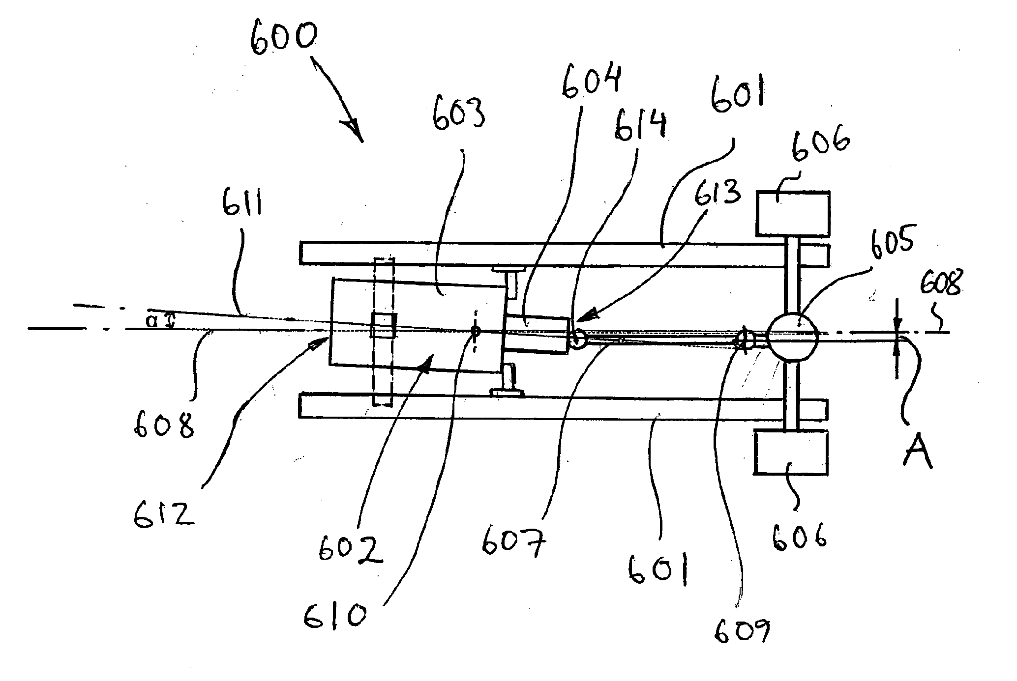
Figure 1 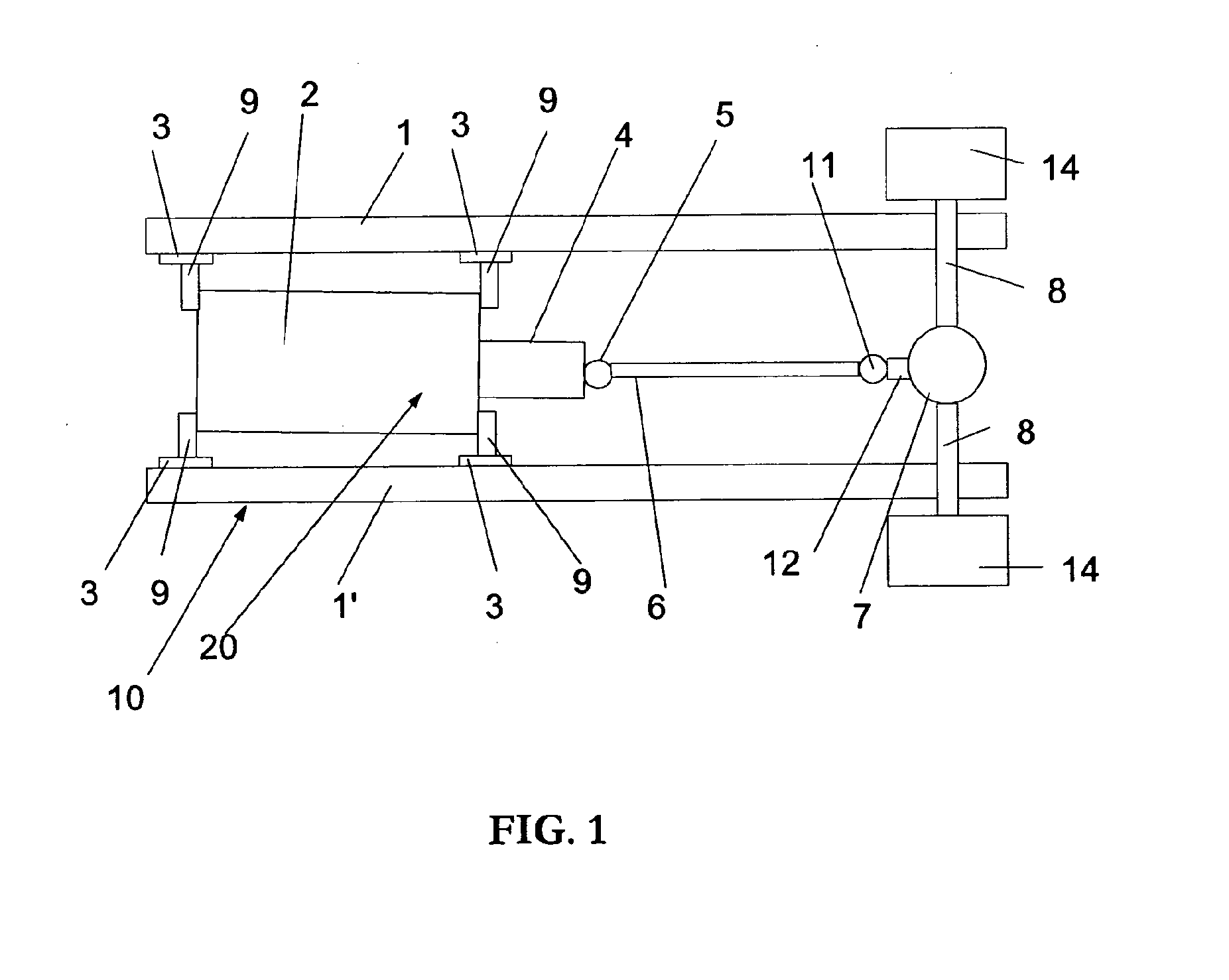
Figure 2 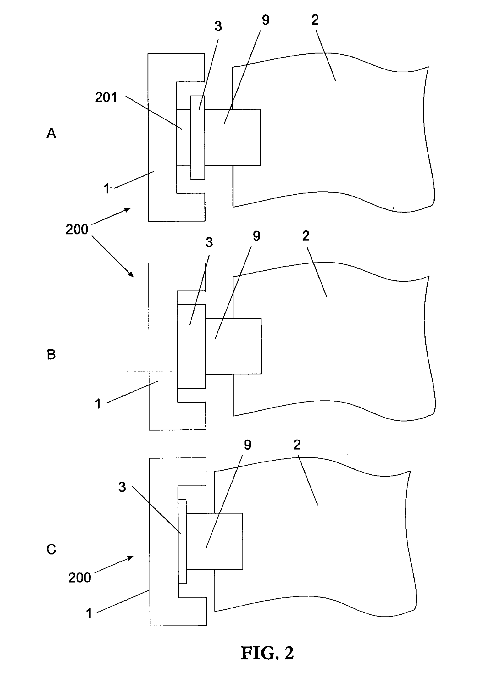
Figure 3
Abstract
Description
BACKGROUND AND SUMMARY
[0001] The present invention relates to a system in a vehicle, and a heavy vehicle comprising a drive unit arranged substantially along a longitudinal geometrical axis of the vehicle.
[0002] A heavy vehicle, such as a truck or a bus, comprises a power transmission system or in other words a drive line for transferring power from an engine to driving wheels of the vehicle. Usually, the drive line comprises a drive unit, i.e. an engine and a gear box, and a propeller shaft and a differential. The drive line is a well balanced optimized system in order to provide power in a safe manner and with low vibrations transferred to the vehicle.
[0003] A truck is often heavy and large, for example weighing several thousand kilograms and has a powerful engine for driving the wheels. During certain unfavorable conditions the high power output transferred by the driveline may cause undesired vibrations of the drive line. Drive line vibration problems may arise when the drive line ...
Examples
Embodiment Construction
[0025]In FIG. 1, the reference numeral 10 generally denotes a frame of a commercial vehicle. The frame 10 is composed of two U-profile longitudinal side members 1, 1′ united by a plurality of cross members (not shown). An engine 2 is mounted together with a gear box 4 on the frame 1 and 1′ by engine supports each comprising an engine bearer 9 and engine cushion 3. The engine and gearbox together form an engine / gearbox assembly 20. A universal joint 5 is mounted on the gearbox 4 and a propeller shaft 6 transmits power from the engine / gearbox assembly 20 to a differential 7 via a second universal joint 11. The differential 7 distributes the engine power to each driving wheel 14 via respective drive shafts 8. The engine 2, gearbox 4, propeller shaft 6, universal joints 5, 11, and differential 7 together form a power generating and transmission system. Other parts may be used in relation to the power transmission system, for instance a propeller shaft 6 bearing (not shown) for guiding t...