
Anchoring structure with concave landing zone
a technology of anchoring structure and landing zone, which is applied in the field of anchoring structure with concave landing zone, can solve the problems of increasing achieve the effects of reducing the chance of paravalvular leakage, less and less invasive, and reducing the chance of suturing the valve around the annulus
Patent Information
- Authority / Receiving Office
- US · United States
- Patent Type
- Applications(United States)
- Current Assignee / Owner
- Publication Date
- 2010-04-22
Smart Images
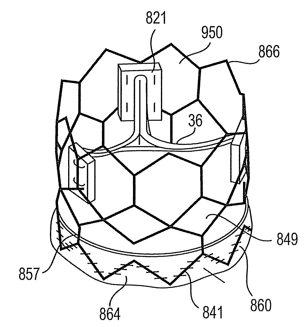
Figure 1 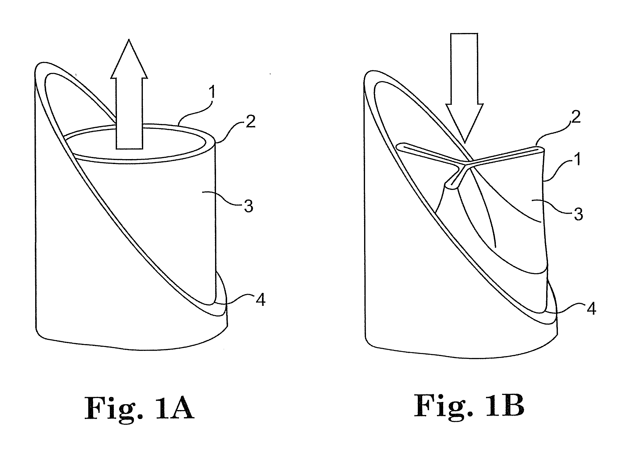
Figure 2 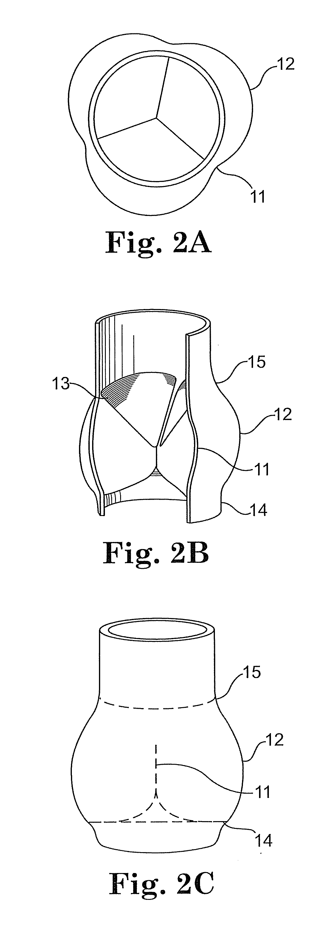
Figure 3
Abstract
Description
[0001] This application is a continuation in part of co-pending U.S. application Ser. No. 11 / 489,663 filed on Jul. 17, 2006, which is a continuation-in-part of application Ser. No. 10 / 680,071 filed on Oct. 6, 2003, now U.S. Pat. No. 7,101,396; and also claims priority to U.S. provisional application Ser. No. 61 / 184,650 filed on Jun. 5, 2009, the entireties of which are hereby incorporated by reference.BACKGROUND OF THE INVENTION
[0002] 1. Field of the Invention
[0003] The invention relates to an anchoring structure for use in minimally invasive bioprosthetic heart valve replacement systems. More particularly, the invention relates to a tubular anchoring structure with an inflow end that includes a concave landing zone that reduces paravalvular leakage.
[0004] 2. Description of the Related Art
[0005] The transport of vital fluids in the human body is largely regulated by valves. Physiological valves are designed to prevent the backflow of bodily fluids, such as blood, lymph, urine, bile, etc....
Examples
Embodiment Construction
[0047]While this invention may be embodied in many different forms, there are described in detail herein various embodiments of the invention. This description is an exemplification of the principles of the invention and is not intended to limit the invention to the particular embodiments illustrated.
[0048]For the sake of consistency, the terms “peak” and “trough” are defined with respect to the proximal and distal ends of the anchoring structure in accordance with the invention. As seen in the Figures, each of the tubular anchoring structures has an inflow end, referred to herein as an inflow rim, and an outflow end, referred to herein as an outflow rim. With respect to the inflow and outflow rims “peaks” are concave relative to the proximal end of the anchoring structure and convex relative to the distal end of the anchoring structure. Troughs, on the other hand, are convex relative to the proximal end of the anchoring structure and concave relative to the distal end of the anchor...